7/22
NT 1401-X00 10 18 B200 Flow Control e
2. GENERAL DATA
2.1 Principle of operation
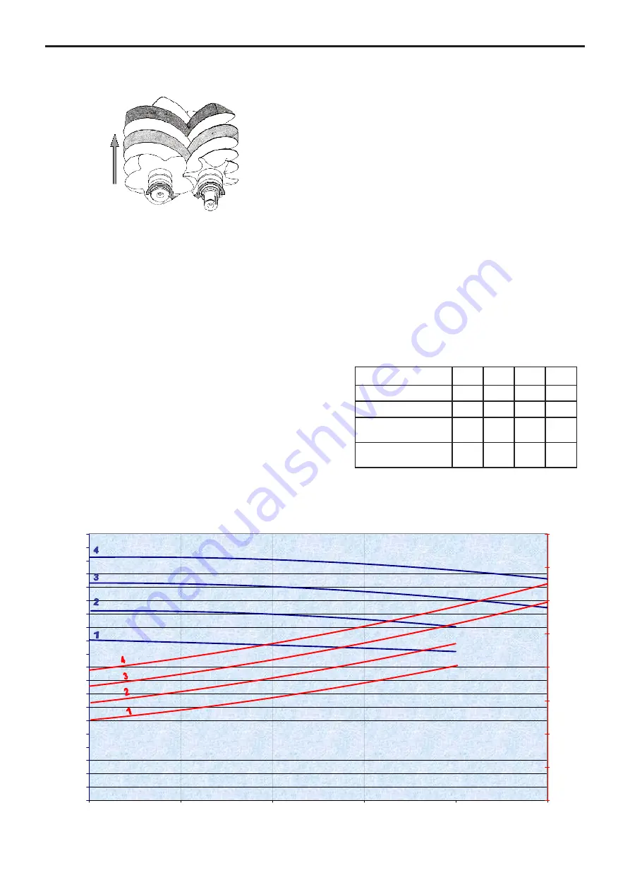
The male screw and the female screw mesh and rotate
in opposite directions inside the casing fitted with inlet
and discharge ports.
Rotation generates a volume increase on the inner face
between threads and grooves, which corresponds to
inlet, and a volume reduction on the upper face, which
corresponds to compression.
On the discharge port side, a set of gears synchronizes
the male screw and the female screw. Thus, the screws
are not in contact. The discharged air does not enter in
contact with any friction part and remains clean and free
from particles.
On the drive shaft side, the female screw or the male screw
according to the inlet shaft direction rotation is driven by
a set of step-up gears.
Oil circulates, lubricating gears and ball bearings.
On the non-drive end side, the ball bearings are lubrica-
ted permanently with grease.
Sealing is provided between lubricated parts and the
compression stage by means of labyrinth seals.
These seals do not enter in contact with the shaft and
are not subject to wear.
Thanks to their rugged design, B200 compressors have a
long service life.
B200 compressors need very limited maintenance,
which reduce vehicle downtime.
B200 versions 12R (1200 rpm) or 10L (1000 rpm) were
defined so as to drive it directly through on the PTO or
with a drive shaft. Thanks to this system, the installation
is lighter and saves space on the side of the vehicle for
other accessories.
2.2 Technical characteristics
The operating characteristics indicate the requirements
to be met, on the B200 compressors, in order for the
equipment to benefit from the associated warranty.
The operating characteristics for the B200 are given in
the indicative operation conditions : ambient temperature
and air inlet temperature 20°C, atmospheric pressure :
1013 mbars.
Speed :
B200
1
2
3
4
12R
(rpm)
840
960
1080
1200
10L
(rpm)
700
800
900
1000
Maximum discharge
pressure (bar)
2
2
2,5
2,5
Maximum inlet
temperature (°C)
40
40
40
40
0
10
20
30
40
50
60
70
80
90
100
110
120
130
140
150
160
170
180
190
200
0
0,5
1
1,5
2
2,5
EXHAUST PRESSURE (bar)
SUCTI
O
N
FLO
W RATE (
m
3/
h)
0
2
4
6
8
10
12
14
16
POWER
(kW)
Suction : 1 atm , 20°C Flow measurement : ISO 5167-2
Characteristics of compressor :


