6
PELLET OR PELLET/ELECTRIC COMBINATION FURNACES
The Caddy Alterna furnace was tested using the guidelines of the EPA Standard.
To optimize the efficiency of your furnace, here are a few advices you should follow when installing or operating your
Caddy Alterna.
Respect the local codes (when in doubt, consult your local dealer);
Make sure your furnace is installed according to the instructions on the certification label;
All controls and adjustments must be performed by a qualified technician. The blower speed must conform
to the recommendations respect the recommended static pressure ranges in the warm air plenum of the
furnace.
1. SAFETY RULES
1.1 GENERAL
REQUIREMENTS
Make sure the chimney outlet and the pipes are clean and in good condition.
DANGER : RISK OF FIRE OR EXPLOSION - DO NOT BURN WASTES, GASOLINE, DRAIN OIL, NAPHTA OIL,
OR FLAMMABLE LIQUIDS OR OTHER UNSUITABLE MATTERS.
DO NOT USE CHEMICALS OR FLUIDS TO START THE FIRE.
WARNING: Risk of fire - Do not operate with fuel loading or ash removal doors open.
HOT WHILE IN OPERATION. KEEP CHILDREN, CLOTHING AND FURNITURE AWAY, CONTACT MAY
CAUSE SKIN BURNS.
1.2
ODOUR FROM THE PAINT
It is normal that smoke and odours emanate from the unit when you first light it. This is due to the paint curing
process. It is recommended to burn the unit at high rate and ventilate the furnace room and the building until the
odours disappear. The smoke is not toxic.
In order to prevent the spread of smoke throughout the
building, this step should be performed before the furnace is connected to the ductwork.
1.3 ASH
DISPOSAL
Ashes must be placed in a metal container with a tight fitting lid. The container should be stored outdoors, well away
from combustible materials. This container should not receive any other type of waste. If the ashes are meant to be
buried in soil, wait until all embers have thoroughly cooled before burying.
W A R N I N G
THE ASH DRAWER AND EXCHANGERS ACCESS PANEL GET VERY HOT.
DO NOT MANIPULATE WITH BARE HANDS.
Summary of Contents for CADDY ALTERNA
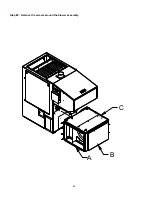
Page 11: ...11 A B C Step 2 Remove the screws around the blower assembly...
Page 49: ...49 6 GENERAL WIRING DIAGRAM...
Page 50: ...50...
Page 51: ...51...


