33
CADDY ADD-ON
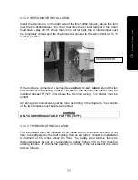
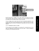
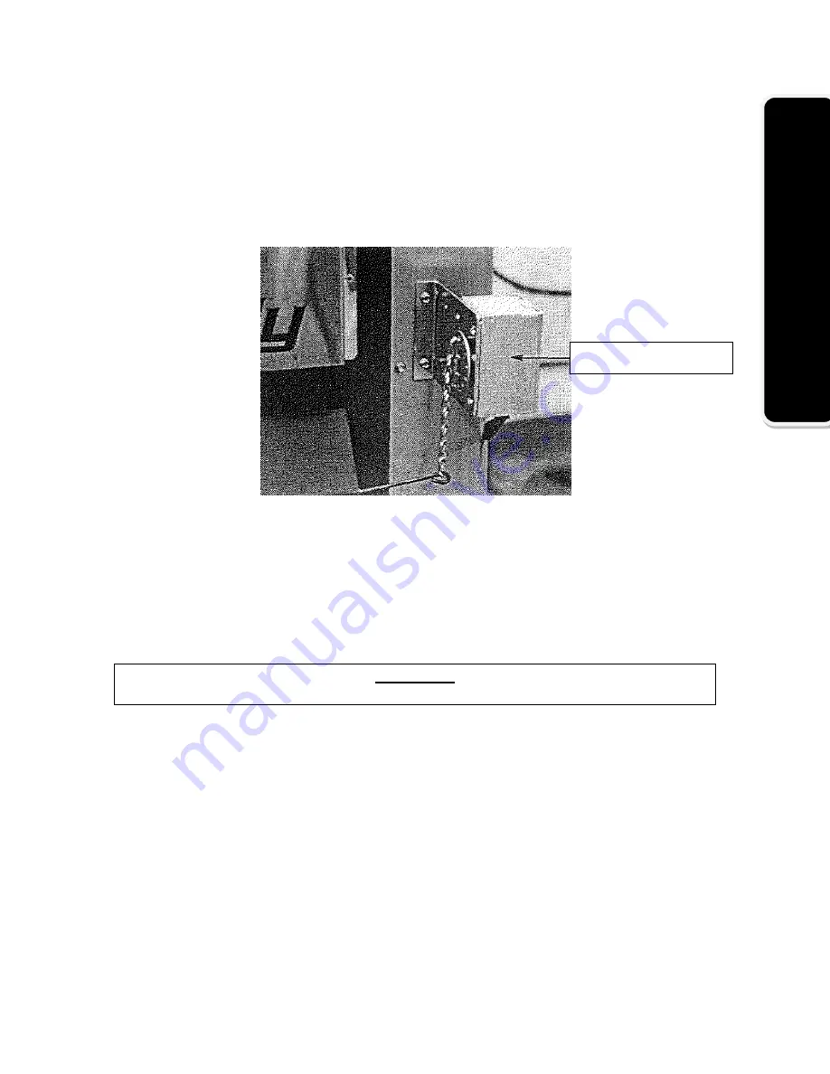
3.1.6.2 SERVOMOTOR INSTALLATION
Install the servomotor on the right side of the front of the furnace; above the door
(use the pre-drilled holes). The chain that links the air inlet damper to the motor
must have a play of 1/8". When there is no call for heat, the air inlet damper must
be completely closed and the chain must be hooked to the servomotor at the “8
o’clock” position.
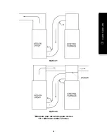
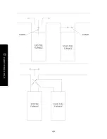
If the ducts are connected in series (See
section 3.1.4.2
,
option 2
) and the fan
limit control of the existing furnace is located in the plenum, the divider must be
installed at least 5" (127 mm) above the fan limit casing. This divider must be
airtight.
All wiring and connections must be done according to the diagram. The controls
of the two furnaces must be interconnected.
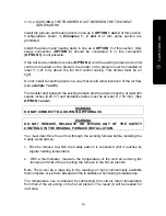
WARNING
ONLY USE WIRES SUITABLE FOR 75°C (167°F).
3.1.6.3 THERMOSTAT INSTALLATION
The thermostat must be installed on an inside wall in a location where it is not
likely to be affected by the draft coming from an air outlet. It must be installed at
a minimum of 55 inches above the floor. The Caddy wood Add-on furnace’s
thermostat must be set to a temperature slightly higher (3°C to 5°C) than the
existing furnace. It controls the opening or closing of the air intake of the wood
Add-on furnace.
SERVOMOTOR
Summary of Contents for Caddy PF01010
Page 16: ...16 CADDY ADD ON Installation Instructions CADDY WOOD ADD ON PF01010 PA08522 ...
Page 22: ...22 CADDY ADD ON Example 1 Example 2 ...
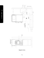
Page 24: ...24 CADDY ADD ON Figure 3 1 4 3 a ...
Page 30: ...30 CADDY ADD ON ...
Page 40: ...40 CADDY WOOD ONLY ...
Page 42: ...42 CADDY WOOD ONLY Figure 3 2 2 3 a ...
Page 52: ...52 CADDY WOOD ELECTRIC Figure 3 3 3 3 a ...
Page 55: ...55 CADDY WOOD ELECTRIC OUTSIDE VIEW OF THE ELECTRIC UNIT ...
Page 68: ...68 Figure 3 4 4 3 a ...
Page 70: ...70 ...
Page 73: ...73 Wiring diagram for Riello Burner ...

