background image


61 


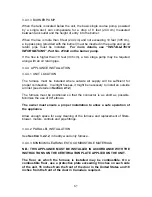
CADDY WOOD/ELECTRIC 

Using a flat 
screwdriver, remove 
the largest knockout 
located on the left 
access panel of the 
electric element. 
 
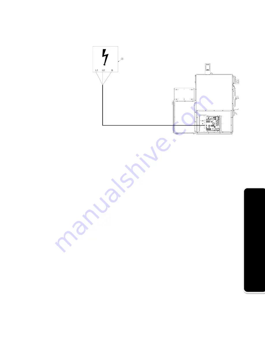
Run the feeder cable 
(not supplied) from 
the house main 
entrance (6) through 
the opening made in 
the left access 
panel. 


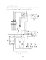
Note: Refer to electrical diagram included with the electrical element for wiring. 


Summary of Contents for Caddy PF01010

Page 1: ...d these instructions carefully before installing and operating your furnace Please keep this document Verified and tested for Canada and the United States by This manual is available for free download on the manufacturer s web site It is a copyrighted document Re sale is strictly prohibited The manufacturer may update this manual from time to time and cannot be responsible for problems injuries or...

Page 2: ...stalling and operating your new furnace It is important that you follow these installation instructions carefully Failure to do so could result in a house fire bodily injuries or even death You may have to get a permit from the local authorities before installing this furnace and the chimney it will be connected to Contact you local building inspector or fire department to know the particular requ...

Page 3: ...ONENTS FOR CADDY WOOD ADD ON 17 3 1 2 SAFETY PRECAUTION 17 3 1 3 INTRODUCTION 17 3 1 4 BLOWER OF THE EXISTING FURNACE 17 3 1 5 APPLIANCE INSTALLATION 18 3 1 5 1 UNIT LOCATION 18 3 1 5 2 MATCHING THE TRANSFER DUCT BETWEEN THE TWO HEAT GENERATORS 19 3 1 5 3 MINIMUM CLEARANCES TO COMBUSTIBLE MATERIALS FOR CADDY WOOD ADD ON 23 3 1 5 4 INSTALLING THE CONNECTING DUCT FROM THE EXISTING FURNACE 25 3 1 5 5...

Page 4: ...DIAGRAM 46 3 2 4 OPERATING INSTRUCTIONS 47 3 2 4 1 CONTROL SYSTEM 47 3 2 4 2 FAN LIMIT CONTROL 47 3 2 5 TECHNICAL DATA CADDY 48 3 2 5 1 GENERAL TECHNICAL DATA 48 3 3 CADDY WOOD ELECTRIC COMBINATION FURNACE 50 3 3 1 NECESSARY COMPONENTS FOR CADDY WOOD ELECTRIC COMBINATION FURNACE 50 3 3 2 INTRODUCTION 50 3 3 3 APPLIANCE INSTALLATION 50 3 3 3 1 UNIT LOCATION 50 3 3 3 2 PARALLEL INSTALLATION 51 3 3 3...

Page 5: ...LECTRICAL CONNECTIONS 71 3 4 5 1 INSTALLATION OF THE FAN LIMIT CONTROL 71 3 4 5 2 SERVOMOTOR INSTALLATION 71 3 4 5 3 THERMOSTAT INSTALLATION 71 3 4 5 4 WIRING DIAGRAM 72 3 4 6 OPERATING INSTRUCTIONS 74 3 4 6 1 FAN LIMIT CONTROL 74 3 4 6 2 COMBUSTION SAFETY CONTROL 74 3 4 6 3 PRE PURGE 74 3 4 6 4 SAFE OPERATION 74 3 4 6 5 TEMPORARY DISENGAGEMENT OF THE BURNER 75 3 4 6 6 COMBUSTION ADJUSTMENT AND VE...

Page 6: ...MAINTENANCE 85 5 1 HEAT EXCHANGERS CARE 85 5 2 CHIMNEY MAINTENANCE 87 5 3 SMOKE PIPE INSPECTION 87 5 4 BLOWER MOTOR MAINTENANCE 87 5 5 FILTERS 87 5 6 DOOR GASKET RELACEMENT 88 6 PART E REMPLACEMENT PARTS 89 6 1 THE GLASS 89 6 2 THE DOOR GASKET 89 6 3 CADDY BRICK LAYOUT 90 7 PART F DUCTS AND DAMPERS DIMENSIONS 92 7 1 DUCTS AND DAMPERS DIMENSIONS EXAMPLES OF CALCULATION 92 8 PART G TROUBLESHOOTING 9...

Page 7: ...learances to combustibles making sure that they correspond to the ones included in this instruction manual Make sure your furnace is installed according to the instructions on the certification label All controls and adjustments must be performed by a qualified technician The blower speed must conform to the recommendations of the Warm Air Heating and Air Conditioning National Association and shou...

Page 8: ...06 w c a barometric draft control should be installed on the smoke pipe Never install a manual damper The barometric control must be adjusted so that the maximum draft measured at the furnace outlet does not exceed 0 06 w c Please note that a draft exceeding 0 06 w c will reduce the efficiency and could produce an uncontrollable fire On the other hand the minimum draft required is 0 04 w c in the ...

Page 9: ...lid The container should be stored outdoors well away from combustible materials This container should not receive any other type of waste If the ashes are meant to be buried in soil wait until all embers have thoroughly cooled before burying 2 4 CREOSOTE BUILD UP AND REMOVAL When wood is burned slowly it produces tar and other organic vapours which when combined with moisture form creosote The cr...

Page 10: ... see Section 4 6 Chimney fire 2 5 SMOKE DETECTOR We highly recommend the use of a smoke detector It must be installed at least 15 feet 4 57 m from the appliance in order to prevent undue triggering of the detector when reloading 2 6 DOOR GLASS To maintain a clean and safe installation do not build your fire too close to the glass or allow logs to lean on the glass Do not operate your furnace at to...

Page 11: ...CE IS IN USE MAINTAIN ALL GASKETS IN GOOD CONDITION IN CASE OF DETERIORATION CONTACT YOUR DEALER FOR A GENUINE REPLACEMENT GASKET 2 9 ASH GRATE You must replace the ash grate if it is damaged and a replacement may be obtained from your dealer The steel cover on the ash grate is meant to optimize the temperature inside the combustion chamber and should only be removed to empty the ashes 2 10 FLUE A...

Page 12: ... DAMPER The barometric damper must be adjusted so that the maximum draft measured at the furnace outlet is limited to 0 06 in w c However the minimum draft to be respected at all times is 0 04 in w c in the evacuation pipe WARNING DRAFT HIGHER THAN 0 06 W C MAY CAUSE AN UNCONTROLLABLE FIRE CAUSES RESTRICTION ...

Page 13: ...r Bathroom fan Ventilated central vacuum system WARNING SUFFICIENT COMBUSTION AIR MUST BE AVAILABLE AT ALL TIMES LACK OF COMBUSTION AIR CONSTITUTES A DANGER NOTE It is recommended to install an outside air inlet with a diameter of at least 4 inches in the room where the heating appliance is installed see drawing next page It is preferable to choose a wall which is not exposed to dominant winds dep...

Page 14: ... THE FAN AND MOTOR CARTERS CAUSING SOME DEFECTS Clean and replace filters as often as required Note The operation cost is higher when using a dirty filter N B THE OWNER OF THE FURNACE IS RESPONSIBLE FOR THE ROOM S AIR QUALITY IN CASE OF NEGATIVE PRESSURE OR TEMPORARY NEGATIVE PRESSURE 2 14 SETTING UP THE UNIT For a safe and quiet operation the furnace must be level in both directions and supported...

Page 15: ...re that nothing has been damaged in the shipping Pull out the wiring kit and the instructions manual from the firebox of the furnace and the accessories from the flue pipe All controls and adjustments must be performed by a qualified technician The blower speed must conform to the recommendations of the Warm Air Heating and Air Conditioning National Association and should respect the static pressu...

Page 16: ...16 CADDY ADD ON Installation Instructions CADDY WOOD ADD ON PF01010 PA08522 ...

Page 17: ...UCTION The wood burning Caddy Add on furnace is approved for in line connection to an existing oil furnace or any gas or electric furnace with a maximum heating capacity of 35 17 kW 120 000 BTU h 3 1 4 BLOWER OF THE EXISTING FURNACE The blower of the existing furnace shall produce an average air flow in the plenum in between 1 150 to 2 000 cfm when the external static pressure is adjusted to 0 2 a...

Page 18: ...A B 139 Installation code for oil burning equipment CAN CGA B149 1 CAN CGA B149 2 Natural Gas Propane Installation Code et Propane Storage Handling Code 3 1 5 1 UNIT LOCATION The furnace must be installed where outside air supply will be sufficient for proper combustion In airtight houses it might be necessary to install an outside air inlet see la Section 2 12 Fresh air intake The furnace must be...

Page 19: ...uct between the existing furnace and the add on must be at least 320 square inches 0 20 m2 and deviations radius must be at least 6 153 mm See OPTION 1 and 2 WARNING DO NOT CONNECT TO A DOWN FLOW FURNACE WARNING DO NOT REMOVE RELOCATE OR BYPASS ANY OF THE SAFETY CONTROLS IN THE ORIGINAL FURNACE INSTALLATION You must determine the air flow through the existing furnace before installing the Caddy wo...

Page 20: ...t E Average heat generator efficiency 0 75 t Temperature rise ºC b Electric furnace 1 21 Re Electrical energy input rate kW t Temperature rise ºC c Gas furnace 1 21 Rg Gas input rate kW Eg Efficiency of a typical atmospheric gas furnace 0 7 4 After the installation of the add on the original numbers must be restored in order to maintain a constant air flow through the furnace ...

Page 21: ...21 CADDY ADD ON Option 1 Option 2 Minimum duct size 260 square inches R Minimum radius 6 inches ...

Page 22: ...22 CADDY ADD ON Example 1 Example 2 ...

Page 23: ...ANCE WITH THE INSTRUCTIONS ON THE CERTIFICATION PLATE APPLIED ON THE UNIT The floor on which the furnace is installed may be combustible On a combustible floor use a protective plate exceeding 8 inches on each side of the unit 16 inches from the front of the door in the United States and 18 inches from the front of the door in Canada is required ...

Page 24: ...24 CADDY ADD ON Figure 3 1 4 3 a ...

Page 25: ...Figure 3 1 4 3 b Otherwise the minimum height is 15 381 mm These dimensions for all hot air furnaces are in accordance with the standards CSA B140 4 UL 391 and UL 727 3 1 5 4 INSTALLING THE CONNECTING DUCT FROM THE EXISTING FURNACE To install the connecting duct from the existing furnace on the left side of your CADDY Add on furnace remove the screws D securing the large panel E on the left side o...

Page 26: ...e the screws D securing the large panel on the right side of the furnace C and secure it to the left side Secure the panel that was on the left side of the furnace E to the right side with the screws kept D Connect the duct ...

Page 27: ...tall the connecting duct from the existing furnace on the right side of your CADDY Add on furnace unscrew the screws A securing the smallest panel B on right side of the furnace you can dispose of the panel Connect the duct ...

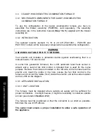
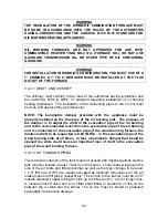
Page 28: ...uates into a separate chimney It s strictly forbidden to connect a solid fuel burning appliance to a chimney already connected to a propane or natural gas appliance Regulation CAN CSA B365 1 WARNING DO NOT INSTALL A MANUAL DAMPER 3 1 6 ELECTRICAL CONNECTIONS The following instructions do not replace those of the local code Installation and verification of this appliance must be done by a qualified...

Page 29: ...control G and the cover on the junction box D Secure the fan limit control bracket provided with your furnace on the top edge of the left or right side of the unit two holes on each side have already been drilled on the edges of the furnace Drill a hole in the plenum across from the hole in the support bracket Slide the fan limit control s probe in the opening on the support bracket and into the p...

Page 30: ...30 CADDY ADD ON ...

Page 31: ... house electrical entrance to the fan limit control s junction box Note It is recommended to connect the Caddy Add on on the same circuit as the existing furnace Pull the red and black wires E out of the junction box through the wire grommet ...

Page 32: ...x D Note To perform the wiring see WIRING DIAGRAM FOR CONNECTION OF THE CADDY ADD ON WITH AN EXISTING OIL FURNACE Section 3 1 5 4 Note For connection with an existing gas or electric furnace remove the fan limit control C from the assembly and use it for low voltage Connection with a gas or electric furnace will require the use of a SPDT 24 volt relay White Rogers 90 370 or the equivalent not incl...

Page 33: ...um the divider must be installed at least 5 127 mm above the fan limit casing This divider must be airtight All wiring and connections must be done according to the diagram The controls of the two furnaces must be interconnected WARNING ONLY USE WIRES SUITABLE FOR 75 C 167 F 3 1 6 3 THERMOSTAT INSTALLATION The thermostat must be installed on an inside wall in a location where it is not likely to b...

Page 34: ...34 CADDY ADD ON 3 1 6 4 WIRING DIAGRAM FOR CONNECTION OF THE CADDY ADD ON WITH AN EXISTING OIL FURNACE ...

Page 35: ...35 CADDY ADD ON 3 1 6 5 WIRING DIAGRAM FOR CONNECTION OF THE CADDY ADD ON WITH AN EXISTING GAS OR ELECTRIC FURNACE ...

Page 36: ...for heat the damper opens and the combustion is stirred up When the furnace gets hot enough the fan limit control activates the blower motor at the speed selected for wood heating When there is no call for heat the air inlet damper must be completely closed and the chain must be affixed to the damper motor at the 8 o clock position With all reserve on the minimum air to be increased depending on t...

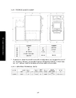
Page 37: ...ATA CADDY ADD ON ADD ON ADD ON A 29 7 8 F 43 1 2 B 26 G 22 C 47 7 8 H 14 1 2 D 28 9 16 FLUE 6 E 24 9 16 WEIGHT 510 Lb GÉNÉRAL TECHNICAL DATA MODELE TEMP BTU HR STATIC PRESSURE VARIABLE WOOD MIN MAX F H20 CADDY ADD ON 78 140 000 0 2 0 5 ...

Page 38: ...38 CADDY WOOD ONLY Installation instructions for CADDY WOOD ONLY FURNACE PF01010 PA08568 PA00500 ...

Page 39: ... The owner must ensure a proper installation to allow a safe operation of the appliance 3 2 2 2 PARALLEL INSTALLATION Parallel installation with another furnace that shares the same ducts system is not permitted in Canada That type of installation is permitted in the USA only In parallel installation the maximum heat input of the existing gas oil or electric furnace should be equal or superior to ...

Page 40: ...40 CADDY WOOD ONLY ...

Page 41: ...INSTRUCTIONS ON THE CERTIFICATION PLATE APPLIED ON THE UNIT The floor on which the furnace is installed may be combustible On a combustible floor use a protective plate exceeding 8 inches on each side of the unit 16 inches from the front of the door in the United States and 18 inches from the front of the door in Canada is required ...

Page 42: ...42 CADDY WOOD ONLY Figure 3 2 2 3 a ...

Page 43: ...therwise the minimum height is 15 381 mm These dimensions for all hot air furnaces are in accordance with the standards CSA B140 4 UL 391 and UL 727 3 2 2 4 CONNECTING PIPE AND MANUAL DAMPER The flue outlet on the Caddy wood only furnace is 6 inch inside diameter In case of excessive draft a barometric draft control must be installed The barometric drafty control must be set so that the draft meas...

Page 44: ...wood only option PA00500 which must be purchased separately WARNING ONLY USE WIRES SUITABLE FOR 75 C 167 F 3 2 3 1 INSTALLATION OF THE FAN LIMIT CONTROL To install the fan limit control refer to the assembly manual supplied with the blower assembly PA08568 sold separately 3 2 3 2 SERVOMOTOR INSTALLATION Install the servomotor on the right side of the front of the furnace above the door use the pre...

Page 45: ...ill be fed from the transformer attached to the junction box of the fan limit assembly and the 120 volts circuit from the house electrical entrance will also be connected to that junction box as per the wiring diagram 3 2 3 3 THERMOSTAT INSTALLATION The thermostat must be installed on an inside wall in a location where it is not likely to be affected by the draft coming from an air outlet It must ...

Page 46: ... Make the connection from the blower to the fan limit control Connect the servomotor and the thermostat to the transformer supplied with the fan limit kit Then feed the fan limit control with the current from the electrical panel of the house ...

Page 47: ...ing 3 2 4 2 FAN LIMIT CONTROL The fan limit control settings may need to be adjusted depending on the installation They are set at 110 F fan OFF and 150 F Fan ON at the factory and these settings will work best in most installations For continuous operation of the blower use the switch located below the fan limit control which controls the low speed either at the on position or the off position It...

Page 48: ...it to wood oil configuration we suggest the use of a 7 chimney this way you wouldn t have to change the chimney In that case a 6 to 7 reducer must be installed at the flue outlet of the furnace 3 2 5 1 GENERAL TECHNICAL DATA MODEL DIRECT DRIVE DEBIT TEMP VAR BTU H STATIC PRESSURE FILTER VENT MOT VIT CFM OF BOIS MIN MAX 2 H2O CADDY DD 10 1 3 4 1300 78 140000 0 2 0 5 25 x 14 x 1 ...

Page 49: ...49 CADDY WOOD ELECTRIC Installation instructions for CADDY WOOD ELECTRIC COMBINATION FURNACE PF01010 PA08568 PA01000 PA01050 ou PA01100 ...

Page 50: ...disc control In some first generation furnaces the L 200 automatic reset heat sensor is absent and a second fan limit control is included that is used for the same purpose Remove the knock out located on the left side of the furnace near the electric unit insert the probe in the hole secure the fan limit control to the furnace and connect the cable 14 2 inside the electric unit at the same locatio...

Page 51: ...UST BE INSTALLED IN ACCORDANCE WITH THE INSTRUCTIONS ON THE CERTIFICATION PLATE APPLIED ON THE UNIT The floor on which the furnace is installed may be combustible On a combustible floor use a protective plate exceeding 8 inches on each side of the unit 16 inches from the front of the door in the United States and 18 inches from the front of the door in Canada is required ...

Page 52: ...52 CADDY WOOD ELECTRIC Figure 3 3 3 3 a ...

Page 53: ... UL 391 and UL 727 3 3 3 4 CONNECTING PIPE AND MANUAL DAMPER See Section 3 2 2 4 in Caddy wood only furnace 3 3 4 ELECTRICAL CONNECTIONS The following instructions do not replace those of the local code Installation and verification of this appliance must be done by a qualified service man All wiring from the service panel to the heating unit must comply with the electrical code in force and all l...

Page 54: ...t should be set slightly higher 3 C or 5 F than the electric thermostat to allow the wood furnace to stabilize the temperature before the electric thermostat calls for heat The bigger the increment the more wood will contribute to the global heating needs This furnace s blower uses a four speed motor one speed LOW is controlled by the manual switch for summer operation Three heating speeds are ava...

Page 55: ...55 CADDY WOOD ELECTRIC OUTSIDE VIEW OF THE ELECTRIC UNIT ...

Page 56: ... with an optional electric element 15 18 or 20 kW The installation must be performed by a qualified professional 1 Remove the screws A securing the electric unit access panel B to the left side of the furnace Keep the screws but you may dispose of the cover 2 Remove the panel C from the electric element option Keep the screws D ...

Page 57: ...slide the electric element assembly E into the left hand side opening in the furnace cabinet To secure the electric element box to the furnace use four of the eight screws A kept in Step 1 You may dispose of the remaining screws 4 Secure the electric element panel C with the screws kept in Step 2 ...

Page 58: ...or right side of the unit two holes on each side have already been drilled on the edges of the furnace Drill a hole in the plenum across from the hole in the support bracket Slide the fan limit control s probe in the opening on the support bracket and into the plenum Secure the fan limit control G on the support bracket with self taping screws not provided ...

Page 59: ...knockout on the right lower corner on the back of the furnace Run the long BX cable from the fan limit control 2 through the middle opening made on the electric element panel Run the short BX cable from the blower 1 through the opening made on the right lower corner on the back of the furnace to the electric element as illustrated below ...

Page 60: ...e servomotor 5 through the top opening made in Step 6 Here s where the cables from Steps 6 and 7 should go through the left electric element access panel Top knockout Cables coming from both thermostats and from the servomotor Middle knockout Cable coming from the fan limit control Bottom knockout Cable coming from the blower The short BX cable from the blower will come from inside the blower box ...

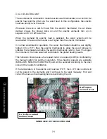
Page 61: ...gest knockout located on the left access panel of the electric element Run the feeder cable not supplied from the house main entrance 6 through the opening made in the left access panel Note Refer to electrical diagram included with the electrical element for wiring ...

Page 62: ...62 CADDY WOOD ELECTRIC 3 3 4 5 WIRING DIAGRAM Refer to electric diagram included with the electrical unit ...

Page 63: ...ONTROL The fan limit control settings may need to be adjusted depending on the installation but they are set at 110 F fan OFF and 150 F Fan ON at the factory and these settings will work best in most installations For continuous operation of the blower use the switch located below the fan limit control which controls the low speed either at the ON position or the OFF position It is not recommended...

Page 64: ...64 Installation instructions for CADDY WOOD OIL COMBINATION FURNACE PF01010 PA08568 PA03050 ou PA03100 ...

Page 65: ...UCTION READ THESE INSTRUCTIONS CAREFULLY BEFORE OPERATING YOUR FURNACE CERTIFIED BY INTERTEK ACCORDING TO CAN CSA B366 1 M91 UL391 3rd EDITION 1995 rev 1999 CAN CSA B212 93 JUNE 2000 CAUTION EXPLOSION OR FIRE HAZARD FOR YOUR SAFETY DO NOT STORE OR USE GASOLINE OR ANY FLAMMABLE LIQUIDS OR VAPORS IN THE VICINITY OF THIS HEATING UNIT DO NOT ATTEMPT TO LIGHT THE BURNER WHEN EXCESS OIL HAS ACCUMULATED ...

Page 66: ...se of the damper is to adjust the draft in the evacuation pipe of the oil burning unit to the recommended level Since the evacuation pipe of the oil burning unit is connected on the evacuation pipe of the wood burning furnace the minimum draft to be respected is 0 04 IN W C in the evacuation pipe of the wood burning side at all times In fact a barometric damper that would be opened too wide could ...

Page 67: ...ion In airtight houses it might be necessary to install an outside air inlet see details in Section 2 12 The furnace must be positioned so that the connector is as short as possible Minimize the use of 90o elbows The owner must ensure a proper installation to allow a safe operation of the appliance Allow enough space for easy cleaning of the furnace and replacement of filters blower motors control...

Page 68: ...68 Figure 3 4 4 3 a ...

Page 69: ... 3 b Otherwise the minimum height is 15 381 mm These dimensions for all hot air furnaces are in accordance with the standards CSA B140 4 UL 391 and UL 727 3 4 4 4 CONNECTING PIPE AND MANUAL DAMPER The pipe connecting the furnace to the chimney must be as short as possible If a deviation is required the use of 45o elbows is highly recommended for a better evacuation of the smoke in the chimney of t...

Page 70: ...70 ...

Page 71: ...o feed the furnace with its own electrical circuit of 15 amps at 120 volts with a breaker see wiring diagram All wiring between electrical components must be of sufficient length It is very important to keep away the wires from sources of intense heat 3 4 5 1 INSTALLATION OF THE FAN LIMIT CONTROL See Section 3 41 Necessary components for caddy wood oil combination furnace 3 4 5 2 SERVOMOTOR INSTAL...

Page 72: ... 3 4 5 4 WIRING DIAGRAM The location of the fan limit control for wood is in the plenum and the fan limit control for oil is located on the panel on the exhaust pipe side Wiring diagram for Beckett Burner ...

Page 73: ...73 Wiring diagram for Riello Burner ...

Page 74: ... reach a certain temperature before the blower starts in order to operate efficiently 3 4 6 2 COMBUSTION SAFETY CONTROL The AFG type oil burner is equipped with an electronic control R7184B1032 including a pre purge function and a new more durable drive motor 3 4 6 3 PRE PURGE When there is a call for heat the burner s fan will run for 15 seconds before the actual ignition takes place to vent the ...

Page 75: ... of the normal cycle FOR ADDITIONAL INFORMATIONS ON OPERATION SEQUENCES OF THE BURNER CONSULT THE BURNER INSTRUCTION MANUAL 3 4 6 6 COMBUSTION ADJUSTMENT AND VERIFICATION To enjoy the efficiency of our oil burning units you must respect the following criterion CHECK LIST SELECTION OF NOZZLE AND HEAD NOZZLE ELECTRODES POSITION IN RELATION TO THE HEAD AND PUMP PRESSURE OIL LINE IS BLEED PRESENCE OF ...

Page 76: ...LEAST 10 TO 15 MINUTES D OVER THE FIRE DRAFT 0 01 TO 0 02 IN W C THE DRAFT OVER THE FIRE MUST BE MEASURED IN THE OPENING OF VISION TUBE S PULSATION TRAP E SMOKE TEST BETWEEN 0 AND 1 ON THE SHELL BACHARACH SCALE TRACES F DRAFT IN THE CHIMNEY 0 02 IN W C TO 0 04 IN W C G PERCENTAGE OF EXCESS AIR 20 TO 40 12 CO2 4 6 O2 H AVERAGE EFFICIENCY OF 80 TO 85 I TIGHTEN ALL THE LOCKING SCREWS AFTER COMPLETING...

Page 77: ...must be adjusted by a qualified technician A proper positioning of the electrodes is important to get an efficient lighting of the oil and and efficient dispersion of the oil jet 3 4 6 9 ELECTRODE SETTING FOR F HEAD 7 16 5 32 1 16 NOZZLE ELECTRODE ...

Page 78: ...RNER DOES NOT APPEAR TO BE OPERATING PROPERLY IMMEDIATELY CONTACT YOUR QUALIFIED SERVICE AGENCY FOR CONSULTATION 6 FOR MORE DETAILS ABOUT THE BURNER REFER TO THE BURNER S MANUAL 3 4 6 10 APPLIANCE START UP The start up must be performed by a qualified technician Make sure the installation is completed and the oil tank has been filled up The oil line must also have been purged CAUTION CLOSE THE BLO...

Page 79: ...e pipe should be cleaned at least once a year 2 The nozzle should be inspected and replaced if needed 3 Handle with care to avoid damaging its surface 4 The electrodes should be adjusted as indicated in the burner manual 5 Lubricate the burner motor bearings twice a year 2 or 3 drops of SAE 20 non detergent lubricating oil 6 The oil filter should be verified annually and replaced if needed Burner ...

Page 80: ...he furnace Does not include the oil burner sold separately MODEL BURNER TYPE BTU INPUT NOZZLE HEAD STATIC PLATE PRESSURE AT THE PUMP H P FAN MOTOR CADDY BECKETT AFG 91 000 0 65 70 O W DELAVAN F3 2 3 4 120 PSI 1 3 H P CADDY RIELLO F3 91 000 0 65 70 O W DELAVAN 120 PSI 1 3 H P CADDY AERO FAF C 2X 91 000 0 65 70 O W DELAVAN 120 PSI 1 3 H P For any additional information consult the certification plat...

Page 81: ...s and light the paper at 2 or 3 different spots as low as possible and leave the door opened about inch until the fire is burning well If lighting fails some smoke could spill out of the furnace through the air inlets 4 2 PREHEATING 1 Once the kindling is burning well or the ember bed stirred up lay 2 or 3 pieces of seasoned cordwood down in a way that the flame can circulate around the logs split...

Page 82: ...NG IT WIDE TO ALLOW STABILISATION OF THE PRESSURE INSIDE THE FURNACE 4 4 FIRST SIGNS OF AN OVERHEATING FURNACE ARE 1 The fire rumbles 2 The smoke pipe turns red 3 Extreme heat emanates from the furnace IF this happens DO NOT OPEN THE DOOR close the air inlet completely and wait for the fire to die down WARNING ALWAYS KEEP THE DOOR AND ASH DRAWER CLOSED EXCEPT FOR LIGHTING RELOADING AND SERVICING T...

Page 83: ...HAT YOU MUST FEAR 4 6 CHIMNEY FIRE A Chimney fire will happen when the flame from an uncontrollable fire ignites the sooth and creosote deposits in a neglected venting system It will often happen when burning cardboard branches or small dry pieces of wood The first signs of a chimney fire are 1 A rumble 2 Smoke pipe becomes extremely hot 3 Sparks or even flames shoot out of the chimney In the even...

Page 84: ...GE To reduce the risk of overheating during a prolonged power outage more than 10 minutes it is recommended to make certain that the air intake damper is closed Open the blower access panel and remove the air filter to improve the circulation of air around the combustion chamber of the Caddy furnace ...

Page 85: ...hangers is easy and does not require tools just remove the decorative facing by just lifting it remove the wing nut that keeps the hinged access panel closed See pictures below Before cleaning the three exchanger pipes 1 pull the baffle forward as on the drawing below Using the scraper 2 clean all three pipes The dirt 4 in the lateral pipes can be pushed forward and it will fall directly into the ...

Page 86: ...86 Cut view of the Caddy wood only furnace ...

Page 87: ...The pipe must be examined carefully to detect any defect or damage The pipe can be reassembled if no defect is detected and defective pipe must be replaced immediately Burn wood only in this furnace As a combustible well seasoned hardwood in 18 logs works best 5 4 BLOWER MOTOR MAINTENANCE After 3 seasons of operation lubricate the motor annually with a few drops of 5W30 oil DO NOT OVERLUBRICATE 5 ...

Page 88: ... maximum adjustment replace the gasket see Section 6 2 THE DOOR GASKET Door adjustment procedure 1 Unscrew completely the locking pin with its nut see picture below 2 To increase the pressure of the door on the gasket turn the handle counter clockwise to decrease the pressure of the door on the gasket turn the handle clockwise until desired pressure is attained 3 Then screw back the locking pin ab...

Page 89: ...ace the glass remove the screws that hold the glass retainers to the door frame and remove the retainers Replace the damaged glass by the new one and reinstall the retainers The genuine glass sold by your dealer will have a new gasket installed on it make sure you install a new gasket if you do not use the PSG replacement part Never clean the glass with a product that could scratch it Use a stove ...

Page 90: ...90 6 3 CADDY BRICK LAYOUT WARNING INSTALL CERAMIC INSULATION PANELS BEFORE LAYING THE BRICKS INSIDE COMBUSTION CHAMBER ...

Page 91: ...91 BRICK LAYOUT QTY 1 ASH GRATE 1 2 BRICK 4 X 8 HD 1 3 BRICK 4 X 9 HD 8 4 BRICK 4 X 8 HD SPECIAL 2 5 BRICK 4 1 2 X 9 HD 23 6 BRICK 1 1 4 X 9 HD 1 7 BRICK 4 1 2 X 9 HD 2 8 1 2 BRICK 4 1 2 X 9 HD 2 ...

Page 92: ...tlet 2 x 12 damper or 4 x 10 For a 6 warm air outlet 2 x 14 damper or 4 x 12 WARM AIR SYSTEM INSTALLATION HOUSE DIMENSIONS Example 28 x 40 bungalow 1 120 sq ft 28 x 40 x 8 8 960 sq ft x 1 8 Ch air hr 16 128 Btu Exposed walls 40 40 28 28 136 x 8 1 088 sq ft x 22 23 936 Btu Number of windows 12 of 3 x 4 144 x 60 8 640 Btu Number of doors 2 x 3 x 7 42 x 100 4 200 Btu 52 904 Btu Non insulated basement...

Page 93: ...he chain that links the damper to the servomotor Rebalance the ventilation system in order to increase the air flow in the room where the thermostat is located Fan start up is too slow Fan ON setting too high Return air is too cold temperatures lower than 65 degrees Limit control not well located on the furnace Lower the temperature starting point Usually the limit control is set at 150 degrees we...

Page 94: ...d only and wood electric 7 If installed in wood oil Outside dimensions of the furnace 26 L x 47 P x 48 H Dimensions of the firebox 17 L x 22 5 P x 16 H Dimensions of the door opening 13 75 L x 10 H Type of door Cast iron with ceramic glass Dimensions of the hot air plenum 24 5 L x 28 25 Dimensions of the cold air plenum 24 5 L x 15 75 Dimensions of ash drawer 12 L x 16 P x 3 H Thickness of steel f...

Page 95: ...for burner Yes Recommended exhaust pipe diameter 5 Exhaust pipe location Left US Gallon 1 US Gallon 0 83 Imperial Gallon Optional blower Blower Wood or wood electric options only 1 3 HP Direct drive 4 speeds 1300 cfm Number of filters 2 Dimensions of the filters 12 L x 24 P x 1 H Top cold air plenum option Material Galvanized steel Dimensions 24 7 8 W x 15 7 8 D x 12 7 8 H Smoke pipe diameter 6 Op...

Page 96: ...our costs covered by this warranty are limited according to the table below The manufacturer at its discretion may decide to repair or replace any part or unit after inspection and investigation of the defect The manufacturer may at its discretion fully discharge all obligations with respect to this warranty by refunding the wholesale price of any warranted but defective parts The manufacturer sha...

Reviews: