11
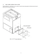
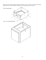
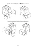
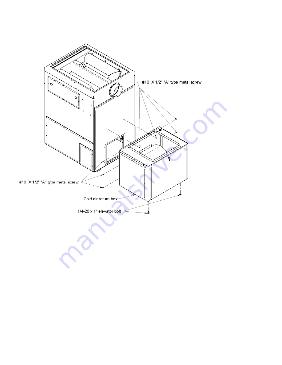
Then, secure the cold air return box to the furnace. To do so, use the 8 screws as shown below. Then, level the cold
air return box by screwing or unscrewing the elevator bolts.
3.2
COLD AIR DUCTING SUPPORT INSTALLATION
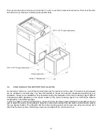
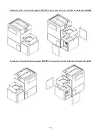
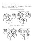
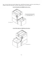
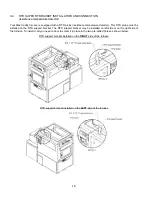
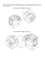
On the cold air return box, you will find two side plates and the cold air return box door. The cold air ducting support
can be configured in several ways. You have the flexibility to choose the desired configuration depending of your
installation. Indeed, some installations have obstacles making the installation of the cold air ducting support difficult.
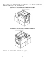
Configurations differ depending on the chosen location of the cold air ducting support. You will find the different
configurations in the following pages.
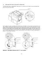
In order to realize the various configurations, you must remove the three screws retaining the side plate where you
wish to install the cold air ducting support. Keep the screws which retained the side plate to install the side plate at
the new desired location. The side plate and the cold air ducting support must be secured using nine screws each
(kept from the previous step). Remaining screws are provided with the cold air return box.
Summary of Contents for MAX CADDY PF01101
Page 38: ...38 7 GENERAL ELECTRIC DIAGRAM WITH BECKETT OIL BURNER ...
Page 39: ...39 8 GENERAL ELECTRIC DIAGRAM WITH RIELLO OIL BURNER ...
Page 42: ...42 ...
Page 45: ......


