18
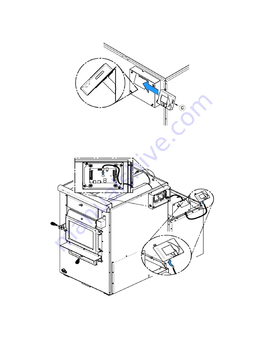
9.3. TOUCHSCREEN INSTALLATION AND CONNECTION
The touch screen is used to operate the system. It must be installed on the support provided at the back of the furnace,
on the same side as the link board housing.
Connect link board with the touch screen using the telecommunication wire provided with the user manual. Plug the
telecommunication wire in connector labeled LCD and pull it out of the board housing through the top grommet. Simply
run the wire on the side of the furnace using the plastic ties supplied with the user manual. Replace the access panel
of the link board. Note that the touch screen is removable if access is restricted.
Summary of Contents for MAX CADDY PF01102
Page 10: ...10...
Page 47: ...47 15 GENERAL ELECTRICAL DIAGRAM...
Page 48: ...48 16 ELECTRICAL DIAGRAM FOR PARALLEL FURNACE...
Page 49: ...49 17 ELECTRICAL DIAGRAM FOR ELECTRIC UNIT...
Page 55: ...55 22 7 DIFFERENT INSTALLATION...
Page 61: ...61 26 ELECTRICAL DIAGRAM BECKETT OIL UNIT...
Page 62: ...62 27 ELECTRICAL DIAGRAM RIELLO OIL UNIT...
Page 64: ...64 28 4 24V ADDITIONNAL EQUIPMENT 28 5 AIR CONDITIONNING DAMPER 28 6 HUMIDIFIER...
Page 65: ...65 28 7 HEAT PUMP 29 EXPLODED VIEW AND PART LIST...
Page 66: ...66...
Page 67: ...67...
Page 68: ...68...
Page 69: ...69...
Page 70: ...70...
Page 71: ...71...
Page 72: ...72...


