10
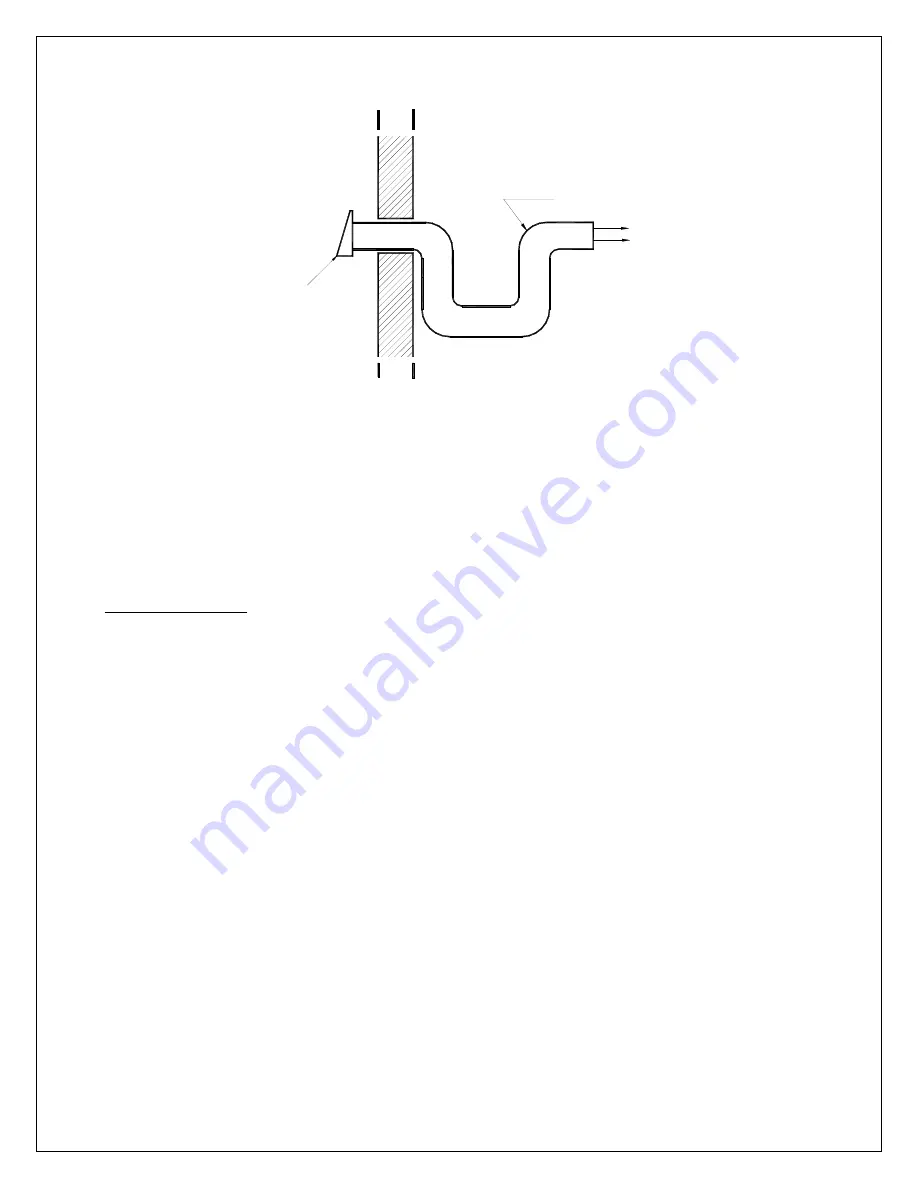
AIR SUPPLY
INSULATED PIPE
EXTERIOR WALL
AIR INLET
N.B. The owner of the furnace is responsible for the room salubrity in case of
negative pressure or temporary negative pressure.
ELECTRICAL CONNECTIONS
The following instructions do not replace those of the local code.
CADDY ADD-ON
Installation and verification of this appliance must be done by a qualified service man.
Mount the fan limit control on the side of the furnace opposed to the transfer duct between the two
heat generators.
Install the damper motor on the upper right side of the front panel (mounting holes are
already drilled).
If the ducts are connected in series (appendix 1, option 2) and the fan limit control of the existing
furnace is located in the plenum, the divider must be installed at least 5" (127 mm) above the fan limit
casing. This divider must be airtight.
All wiring and connections must be done according to the diagram. The controls of the two
furnaces must be interconnected.
ATTENTION : ONLY USE WIRES SUITABLE FOR 75°C (167°F).
THERMOSTAT
The thermostat must be installed on an inside wall in a location where it is not likely to be
affected by the draft coming from an air outlet. It must be installed at a minimum of 55 inches
above the floor. The two thermostats on a combined system must be installed at the same
height. In normal bi-energy operation, the wood system thermostat should be set 2
o
to 3
o
higher than the electric system thermostat.


