Chapter 9: Breakout Board
RS-232 / UART Devices
134
Psion Teklogix Omnii HDK User Manual
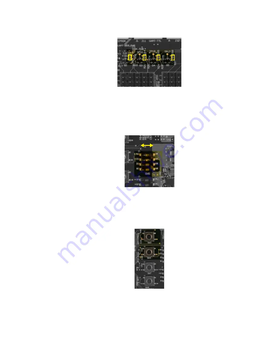
Figure 9.11 GPIO LED Indicators (DS3, DS4, DS5, DS6)
DIP switches 1 and 2 on switch bank SW5 are connected to GPIO lines 4 and 5, respectively. One
end of each DIP switch is pulled high with 10 kohm to 3.3 V, and the other end is grounded. With
the DIP switch in position 1, the corresponding line reports High status to Omnii. Moving the
switch over to position 2 changes the line status to Low. VSYS 3.3 V (HDK_3V3) power must be
enabled to power these switches.
DIP switches 3 and 4 on bank SW5 are not connected.
Figure 9.12 GPIO DIP Switch Bank (SW5)
The tactile switches SW3 and SW4 are connected to GPIO lines 6 and 7 respectively. The default
position of each switch is pulled high with 10 kohm to 3.3 V, and the other position is grounded.
With the switch unpressed (position 1), the corresponding line reports High status to Omnii. Press
the switch down to position 2 to change the line status to Low. VSYS 3.3 V (HDK_3V3) power
must be enabled to power these switches.
Figure 9.13 GPIO Tactile Switches (SW3 & SW4)
9.7
RS-232 / UART Devices
This section describes how to configure the breakout board to test serial devices.
1
2
3
4
POS 1 POS 2
SW3
SW4
Summary of Contents for OMNii HDK XT10
Page 4: ......
Page 10: ......
Page 12: ......
Page 18: ......
Page 20: ......
Page 24: ......
Page 26: ......
Page 32: ......
Page 72: ......
Page 90: ......
Page 92: ......
Page 116: ......
Page 124: ......
Page 126: ......
Page 130: ......
Page 132: ......
Page 154: ......
Page 168: ......
Page 170: ......
Page 182: ......
Page 184: ......
Page 188: ......


