W W W . P S S O . D E
20
4
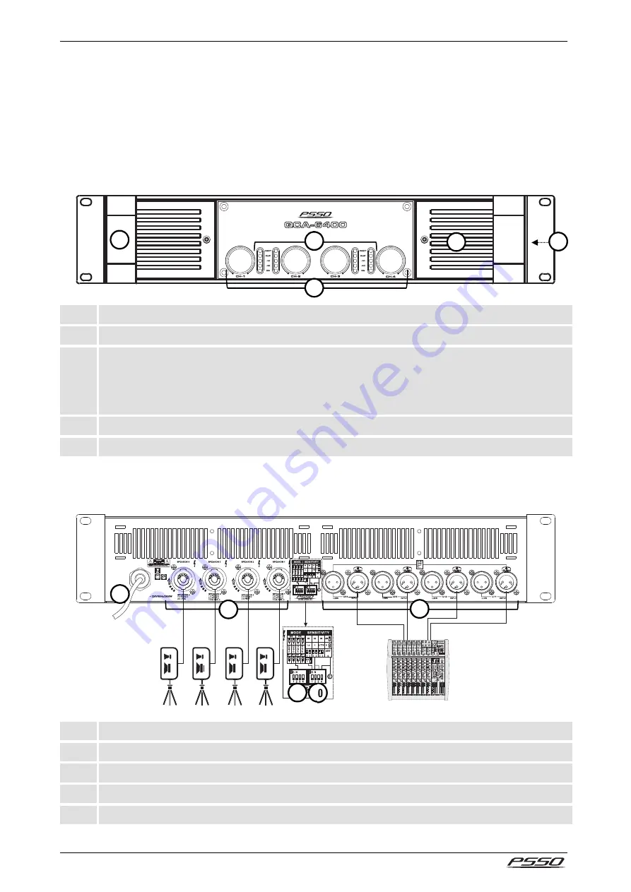
OPERATING ELEMENTS & CONNECTIONS
This user manual describes the front panel of the QCA-6400 as a reference. Illustrations and features of the
other model are comparable.
Front Panel
1
Handle
2
Level controls channel 1-4
3
Display LEDs channel 1-4
• PROT: protective circuit is active
• CLIP: overload
• -10 dB, -40 dB: input level indication
• ON: power indication
4
Power on/off
5
Air strainer
Rear Panel
6
Mains cable
7
Speaker connectors channel 1-4
8
Input jacks with feed-through outputs channel 1-4
9
DIP switches operating mode
10
DIP switches input sensitivity with LED
1
4
2
3
5
6
7
8
9
10


