W W W . P S S O . D E
23
Example for the calculation number of speakers/impedance
Number of speakers
≙
≙
≙
≙
Impedance
1
speaker at
8
Ω
8
Ω
2
speakers a
8
Ω
each
4
Ω
(parallel)
2
speakers a
8
Ω
each
16
Ω
(in line)
3
speakers a
8
Ω
each
2.66
Ω
(parallel)
3
speakers a
8
Ω
each
24
Ω
(in line)
4
speakers a
8
Ω
each
2
Ω
(parallel)
The input impedance of the speaker systems should at least be the same or even higher than the output
impedance of the amplifier.
Information on choosing appropriate speaker
cables
• Speaker systems must only be connected via sufficiently dimensioned cables. Too thin cables lead to cable
heatup or enormous power loss and loss in sound quality.
• For all speaker systems up to 400 Watts, we recommend a cable diameter of 2.5 mm², for all other speaker
cables 4 mm².
• A high damping factor of your amplifier supplies a clear sound reproduction. Unnecessarily long and thin cables
will influence the damping factor and thus the low frequencies in a negative way. In order to safeguard good
sound quality, the damping factor should lie around 50. The longer a cable has to be, the thicker it should be. In
this respect, a damping factor of 200 will be reduced to 47 (8 ohms) when using a 10 m long, 2.5 mm² speaker
cable. The power loss at 8 ohms is 1.63 %, at 4 ohms 3.25 % and at 2 ohms even 6.5 %.
• The maximum cable length is 30 meters.
General information on installing cables
• Always treat cables carefully and protect them from damages during transportation.
• Install cables always in a structured way and protect them from damage.
• Cables must be installed in a way that no person can stumble over them. Always fix cables with an appropriate
tape.
• Cables should be installed directly (no loops, S-shaped overlengths).
• Always install cables far away from power cables (never closely parallel).
• Never put heavy objects like speaker systems, flightcases etc. on cables.
• Never operate cables wound up.
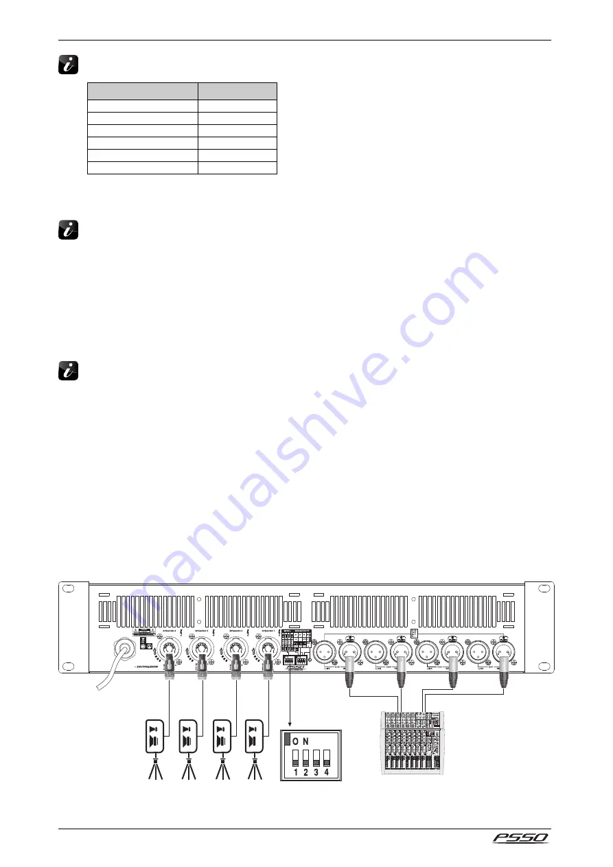
Stereo Operation
In stereo mode, the amplifier can operate four speakers or four speaker groups independently of each other.
The highest output power during is achieved by connecting 2
Ω
speakers. With 4
Ω
and 8
Ω
speakers the
output power will be slightly reduced. For this operating mode, set the DIP switches
MODE 1-4
to their lower
position. Note: At channel 1 and channel 3, it is possible to take off the signal of channel 2 and channel 4
respectively from pins 2+/2-.


