11984 Rev 01
Page 3 of 4
5.1 Maintenance
This pressure drop is measurable by the transducer, and would result in a measurement offset
from the actual process pressure if the transducer is left uncalibrated. The transducer must be
recalibrated to zero out the presence of the offset so that the actual process measurement is
realized.
I
- Caution: Do not block the transducer fittings or the sense tubing when it is attached to
the SENTRY fitting.
The nitrogen purge is supplied to the transducer through a regulator and a precision needle
valve. If the transducer fitting, or sense tube is blocked the line (and the transducer) will quickly
pressurize. This can over-pressurize and cause permanent damage to the capacitive shell and
diaphragm used in the transducer design.
To recalibrate the transducer the following tools will be required: Allen wrench set, digital
voltmeter (accurate to millivolts) and a 1/8" non-conductive screw driver.
I
Note: Electrical power and nitrogen flow must be maintained during this procedure.
Open the top cover of the SENTRY 1510 by removing the four button head screws. Lift the
cover straight up off the controller body.
1. Attach the new length of sense tubing to the barbed fitting. Stretch out the sense tubing so
it is straight with no kinks or bends. Leave the process end of the tube open to the room.
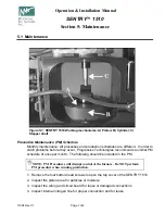
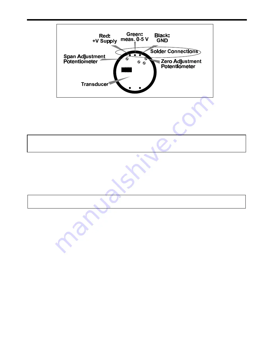
2. Locate the transducer PC board. (See Figure 5-3). There are two potentiometers mounted
on the circuit board, which allow for "zero-adjust" and "span" adjustments. These are
marked in Figure 5-3.
3. The solder wire connections are shown in Figure 5-3. Use a digital volt meter to measure
the transducer signal by measuring the voltage between the "GND" and "meas"
connections (between the black and green wires). The voltage will likely be a small non-
zero number on the order of several hundredths of a volt. When calibrated, the transducer
voltage signal should be between 0.009 and 0.011 VDC when the sense tube is open
ended to the room.
4. Locate the zero-adjustment potentiometer from Figure 5-3. Using a screwdriver, adjust the
pot to about 0.01 V.
5. The transducer is now recalibrated. Replace the top cover of the SENTRY 1510, and
install the process end of the sense tube. The system is now ready for testing.
Figure 5-3:
SENTRY 1510 alternative sensor and electronics.


