background image

TPUH-PSU12-UL: Integrated Switching Power Supply         


PTN Electronics                                  2                                      www.PTN-electronics.de 

2. Specification 

Input & Output 

Input Port 

AC1 & AC2 

Input Voltage 

100~240VAC 50~60Hz 

Output Port   

Total 12 DC port (2-Pin phoenix connectors) 

Output Voltage 

5V, 12V or 24V can be selectable. 

Output Voltage Range 

5V: 4.75~5.25V 

12V: 11.4~12.6V 

24V: 22.8~25.2V 

Maximum output power 
consumption of signal channel 

5V:12W; 12V:15W; 24V:15W 

Maximum output power 
consumption for single supply 

180W 

Maximum output power 
consumption for dual supply 

180W 

Control Part 

Buttons Control 

Front Panel: 01~12, total 12 buttons. 

Rear Panel: Total 12 TACT Switches, named 

SELECT

RS232 Control 

RS232 port (3-Pin phoenix connector). 

Baud rate support 9600. 

GUI Control 

TCP/IP port (RJ45) 

Default IP: 

192.168.0.178 

Port No.: 4001 

General


Temperature 

0 ~ +50


Humidity 

10% ~ 90% 

Dimension (W*H*D) 

437mm x 44mm x 357mm 

Net Weight 

4.2Kg 


Summary of Contents for TPUH-PSU12-UL

Page 1: ...www PTN electronics de TPUH PSU12 UL Integrated Switching Power Supply All Rights Reserved Version TPUH PSU12 UL_2018V1 3 User Manual ...

Page 2: ...ual are acknowledged as the properties of the trademark owner No part of this publication may be copied or reproduced without the prior written consent of PTN Electronics Limited FCC Statement This equipment generates uses and can radiate radio frequency energy and if not installed and used in accordance with the instructions may cause harmful interference to radio communications It has been teste...

Page 3: ...ose the unit to rain moisture or install this product near water Do not put any heavy items on the extension cable in case of extrusion Do not remove the housing of the device as opening or removing housing may expose you to dangerous voltage or other hazards Install the device in a place with fine ventilation to avoid damage caused by overheat Keep the module away from liquids Spillage into the h...

Page 4: ... near any heat sources such as radiators heat registers stoves or other apparatus including amplifiers that produce heat 9 Do not defeat the safety purpose of the polarized or grounding plug A polarized plug has two blades with one wider than the other A grounding plug has two blades and a third grounding prong The wide blade or the third prong is provided for your safety If the provided plug does...

Page 5: ...ssories specified or provided by the manufacturer such as the exclusive supply adapter battery etc 19 WARNING Please refer the information on exterior bottom enclosure for electrical and safety information before installing or operating the apparatus 20 WARNING To reduce the risk of fire or electric shock do not expose this apparatus to rain or moisture The apparatus shall not be exposed to drippi...

Page 6: ...re not provided with the apparatus the installation shall be carried out in accordance with all applicable installation rules Or 27 This lightning flash with arrowhead symbol within an equilateral triangle is intended to alert the user to the presence of non insulated dangerous voltage within the product s enclosure that may be of sufficient magnitude to constitute a risk of electric shock Warning...

Page 7: ... 4 4 System Connection 5 4 1 Usage Precaution 5 4 2 System Diagram 5 5 System Operation 6 5 1 Button Control 6 5 2 RS232 Control 6 5 2 1 RS232 Control Software 6 5 2 2 Basic Setting 7 5 2 3 RS232 Communication Command 8 5 3 GUI Control 12 5 3 1 Control Menu 13 5 3 2 Voltage Setting Menu 14 5 3 3 Network Menu 14 5 3 4 Password Menu 15 5 3 5 GUI Update 15 6 Panel Drawing 16 7 Troubleshooting Mainten...

Page 8: ...CT Switch on rear panel RS232 command or GUI 1 1 Features Double input channel designed for ensuring the stable AC source Total 12 output channels and each channel has three kinds of output voltage 5 12 24VDC can be selected Output channels can be switch on off by via the front panel buttons RS232 commands or GUI Output voltage 5 12 24VDC can be selected via the TACT Switch on rear panel RS232 com...

Page 9: ...5 2V Maximum output power consumption of signal channel 5V 12W 12V 15W 24V 15W Maximum output power consumption for single supply 180W Maximum output power consumption for dual supply 180W Control Part Buttons Control Front Panel 01 12 total 12 buttons Rear Panel Total 12 TACT Switches named SELECT RS232 Control RS232 port 3 Pin phoenix connector Baud rate support 9600 GUI Control TCP IP port RJ45...

Page 10: ...he input voltage is too low or too high 01 12 Output channel switching buttons and Activity LEDs 12 in total Press the button to trun on off the corresponding channel and the corresponding LED will turn green and keep on Long press the button for 3 seconds or more to lock unlock the corresponding channel and then the corresponding LED will flash 3 times Note Pictures shown in this manual are for r...

Page 11: ...losed Blinking fastly when the current channel is short circuit or over voltage RS232 Serial port 3 Pin phoenix connector connect with a control device such as PC to control the product via RS232 commands TCP IP Ethernet port connect with PC to control the product via GUI AC1 AC2 2 AC input channels Input voltage is AC100 240V Note Pictures shown in this manual are for reference only different mod...

Page 12: ...ll of the power switches plugs sockets and power cords should be insulated and safe All devices should be connected before power on 4 2 System Diagram AC100V 240V Tx Rx RS232 TCP IP 24V AC100V 240V AC1 AC2 DC 12V 5V SELECT 24V DC 12V 5V SELECT 24V DC 12V 5V SELECT 24V DC 12V 5V SELECT 24V DC 12V 5V SELECT 24V DC 12V 5V SELECT 24V DC 12V 5V SELECT 24V DC 12V 5V SELECT 24V DC 12V 5V SELECT 24V DC 12...

Page 13: ...age as 5V 12V or 24V Note After switching the output voltage the output channel will be turned off based on overvoltage protection control and it need to be turned on again via the corresponding output channel switching button on front panel Restore Factory Defaults On rear panel simultaneously long press SELECT on channel 01 and channel 02 for 3 seconds or more the device will be restored to fact...

Page 14: ...software CommWatch exe as example The icon is showed as below The interface of the control software is showed as below Please set the parameters of COM number bound rate data bit stop bit and the parity bit correctly and then you are able to send command in Command Sending Area Parameter Configuration area Monitoring area indicates if the command sent works Command Sending area ...

Page 15: ...Open x Switch off the output channel x x 1 12 x Closed Output x V y When y NULL Set the output voltage as x for all output channels x 5 12 24 All Output x V When y 1 12 Set the output voltage as X for the output channel y x 5 12 24 y Output x V Status x When x NULL query the on off status of all output channels 01 Open 02 Closed 03 Closed When x 1 12 query the on off status of the output channel x...

Page 16: ... N N N N N N Lock N N N N N N N N N N N N Clear x When x NULL clear the data of all Group Clear All When x 1 5 clear the data of the Group x Clear F x QueryGroup x When x NULL query all groups Out 01 02 03 04 05 06 07 08 09 10 11 12 Vm1 12 12 12 12 12 12 12 12 12 12 12 12 Vm2 XX XX XX XX XX XX XX XX XX XX XX XX When x 1 5 query the group x Out 01 02 03 04 05 06 07 08 09 10 11 12 Vm x 12 12 12 12 1...

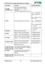
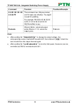
Page 17: ...ion Query the software version V x x x Lock x When x NULL lock all channels Locking all channel When x 1 12 lock the channel x Locking x channel Unlock x When x NULL unlock all channels Locking all channel When x 1 12 unlock the channel x Locking x channel LockKeyboard x When x 0 unlock the front panel Unlocking keyboard When x 1 lock the front panel Locking keyboard FA XX XX XX XX XX XX XX XX XX ...

Page 18: ...FB 54 50 55 48 2D 50 53 55 31 32 00 00 00 20 00 00 FE TPUH PSU12 UL Rebootx When x NULL reboot all output ports When x 1 12 reboot the output port x Rebootx Note After sending the Output x V y to change the output voltage the corresponding output channel will be switch off the command x should be sent to switch on this output channel again After sending the LockKeyboard x to lock the front panel t...

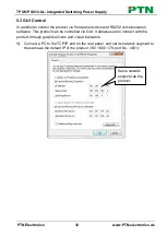
Page 19: ... button and RS232 communication software This product can be controlled via GUI It allows users to interact with the product through graphical icons and visual indicators 1 Connect a PC to the TCP IP port on the rear panel and set its network segment to the same as the default IP of the product 192 168 0 178 port No 4001 Same network segment as the product ...

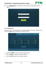
Page 20: ...e log in interface shown as below 5 3 1 Control Menu Type user name user and password user default setting on the log in interface and then click Login to enter Control menu shown as below Select the ON OFF to switch on off the output channel Click the All On to switch on all output channels Click the All Off to switch off all output channels ...

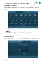
Page 21: ... Voltage Setting on the top of page to enter voltage setting menu shown as below Lock Unlock the output channel When the port is locked its voltage cannot be switched Select 5V 12V or 24V output voltage for each output channel 5 3 3 Network Menu Click Network on the top of page to enter network setting menu shown as below ...

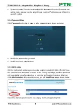
Page 22: ... enter password menu shown as below Modify the password as you need Lock Unlock front panel buttons 5 3 5 GUI Update GUI for the Scaler Switcher supports online update in http 192 168 0 178 100 Type the username and password the same as the GUI log in settings modified password will be available only after rebooting to log in the configuration interface After that click Administration at the sourc...

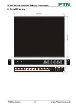
Page 23: ... 10 11 12 AC 2 AC 1 AC100V 240V Tx Rx RS232 TCP IP 24V AC100V 240V AC1 AC2 DC 12V 5V SELECT 24V DC 12V 5V SELECT 24V DC 12V 5V SELECT 24V DC 12V 5V SELECT 24V DC 12V 5V SELECT 24V DC 12V 5V SELECT 24V DC 12V 5V SELECT 24V DC 12V 5V SELECT 24V DC 12V 5V SELECT 24V DC 12V 5V SELECT 24V DC 12V 5V SELECT 24V DC 12V 5V SELECT 437 mm 357 mm 44 mm ...

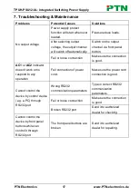
Page 24: ...ake sure the connection is good AC1 or AC2 indicator doesn t work or no respond to any operation Fail connection of power cord Make sure the power cord connection is good Cannot control the device by control device e g a PC through RS232 port Wrong RS232 communication parameters Type in correct RS232 communication parameters Fail or loose connection Make sure the connection is good Broken RS232 po...

Page 25: ...egment Modify control PC s network segment to the same with the TCP IP port The port No are wrong The correct port No is 4001 Fail or loose connection Make sure the connection is good Broken TCP IP port Send it to authorized dealer for checking Note If your problem still remaining after following the above troubleshooting steps please contact your local dealer or distributor for further assistance...

Page 26: ...y Normal wear and tear Use of supplies or parts not meeting our specifications No certificate or invoice as the proof of warranty The product model showed on the warranty card does not match with the model of the product for repairing or had been altered Damage caused by force majeure Servicing not authorized by distributor Any other causes which does not relate to a product defect Shipping fees i...

Page 27: ...TPUH PSU12 UL Integrated Switching Power Supply PTN Electronics www PTN electronics de ...

Page 28: ...Distributed by U T E www PTN Electronics de ...

Reviews: