background image


26 

Rev 2.0 6/21 

Network Connection 

1.


Operating Environment 

Operating System: Windows 2000 / 2003 / XP / Vista / 7 / 8.1 / 10, Mac Catalina and later 

Network Protocol: TCP/IP 

Client PC: P4 / 128M RAM / 40GHD / support for scaled graphics card, support for DirectX8.0 or more advanced version.  

2.


Equipment Installation 

1.  Connect the camera to your network via a CAT5 or CAT cable directly to your network switch. 
2.  Turn on the camera. 
3.  Once powered on, the orange network light will illuminate and the green light will start flashing.  

3.


Network Connection 

Connect the camera & PC to the LAN as shown below. 


Connections to LAN via CAT5 or CAT6 cable 


Summary of Contents for PT12X-NDI-GY-G2

Page 1: ... HX using NDI 4 User Manual Model Nos PT12X NDI GY G2 PT12X NDI WH G2 V2 0 English Please check ptzoptics com for the most up to date version of this document NewTek NDI NDI 4 NDI HX are all registered trademarks by Vizrt Group ...

Page 2: ...ction 26 Assigning an IP Address 27 Using the Upgrade Tool 27 Discovering your Network Info 30 Camera Web Interface 31 PTZOptics HTTP CGI Camera Control 37 Photobooth Functionality 39 Maintenance and Troubleshooting 40 Certifications 41 Changelog 41 Copyright Notice The entire contents of this manual guide whose copyright belongs to PTZOptics may not be cloned copied or translated in any way witho...

Page 3: ... clean it with diluted neutral detergent do not use any type of solvents which may damage the surface Warning Electrical Safety Installation of an operation must be in accordance with national and local electric safety standards Do not use any power supply other than the one originally supplied with this camera Polarity of Power Supply The power supply output for this product is 12V DC with a maxi...

Page 4: ...lled and used in accordance with the instruction manual may cause harmful interference to radio communications FCC Caution Any changes or modifications not expressly approved by the party responsible for compliance could void the user s authority to operate this equipment Operation is subject to the following two conditions 1 This device may not cause harmful interference and 2 this device must ac...

Page 5: ... streaming control 8 HDMI HDMI ver 1 3 connection 9 SDI 3G SDI connection 10 USB 2 0 Low level USB power not recommended for use 11 DC12V DC 12V power connection 12 Power switch Power camera on off SYSTEM SELECT DIAL 0 1080p 60 8 720p 30 1 1080p 50 9 720p 25 2 1080i 60 A 1080p 59 94 3 1080i 50 B 1080i 59 94 4 720p 60 C 1080p 29 97 5 720p 50 D 576i 30 6 1080p 30 E 480i 30 7 1080p 25 F 720p 59 94 Af...

Page 6: ...eous NDI HX IP network streaming 3G SDI HDMI 1 3 o NDI HX Full HD network streaming up to 1080p 60 frames per second o 3G SDI Full HD video output up to 1080p 60 frames per second o HDMI 1 3 Full HD video output up to 1080p 60 frames per second o RTSP RTMP RTMPS streaming using H 264 H 265 or MJPEG o Line level audio embeds over NDI HX network stream HDMI Uses AAC audio encoding for better sound q...

Page 7: ...MPTE 424M standard 1 x HDMI version 1 3 SD Output 1 x CVBS RCA jack 1Vp p 75Ω Network Interface 1 x RJ45 10 100 1000M Adaptive Ethernet ports Audio Interface 1 x 3 5mm audio interface Line In NDI HX IP Network stream only Unbalanced stereo USB 1 x USB 2 0 type A Communication Interface 1 x RS 232 In 8 pin mini DIN Max Distance 30m Protocol VISCA Pelco D Pelco P 1 x RS 232 Out 8 pin mini DIN Max Di...

Page 8: ...mera is setup on a LAN you can utilize the NDI HX connection Two Easy Steps 1 Download and install the latest NDI Tools 2 Select your camera within the NDI HX compatible device Step 1 Download and install the latest NDI HX Tools from https www ndi tv tools Step 2 Optional Configure your camera settings from the NDI Config tab in the camera s web interface Step 3 Select your camera The NDI feed wil...

Page 9: ... button is released or the limit is reached 3 Focus Control Auto Focus Mode Press AUTO Manual Focus Mode Press MANUAL Focus Far Press FAR Focus Near Press NEAR Press and hold the Near or Far button to continue focusing in or out The focusing stops as soon as the button is released or the limit is reached 4 Backlight L R Set P T RST Controls Reverse Pan Control Press L R SET 1 Standard Pan Control ...

Page 10: ...Select 4 10 Standby Control Enable Standby Mode Press Disable Standby Mode Press 11 Camera Shortcuts 1 Display OSD menu in English 3 Display OSD menu in Chinese 4 Show IP address 6 Quickly restore the default settings 8 Show the camera version 9 Quickly set mount mode flip normal MANUAL Resets IP information to default 4 Enable Dynamic IP address L R SET 1 STD Normal Pan controls L R SET 2 REV Rev...

Page 11: ...10 Rev 2 0 6 21 Dimensional Drawings mm ...

Page 12: ... 6 GND 7 IR OUT 7 NC 8 NC 8 NC To utilize an RS 485 connection you will need an unterminated two 2 conductor cable 1 First connect the positive red wire to the camera s positive phoenix connector port left 2 Then connect the negative black wire to the camera s negative phoenix connector port right 3 Next connect the positive and negative wires to the positive and negative ports on your joystick co...

Page 13: ...e camera can be controlled via RS 232 The parameters for RS 232C are as follows Baud rate 2400 4800 9600 or 38400 bps Start bit 1 bit Data bit 8 bits Stop bit 1 bit Parity Bit none RS 485 Communication Control The camera can be controlled via RS 485 Half duplex mode with support for VISCA Pelco D or Pelco P protocol The parameters of RS485 are as follows Baud rate 2400 4800 9600 or 38400 bps Start...

Page 14: ...dicates that two sockets are already being used executing two commands and the command could not be accepted when received Command Canceled z0 6y 04 FF y Socket No Returned when a command which is being executed in a socket specified by the cancel command is canceled The completion message for the command is not returned No Socket z0 6y 05 FF y Socket No Returned when no command is executed in a s...

Page 15: ...ce Trigger CAM_RGain Reset 8x 01 04 03 00 FF Manual control of red gain Up 8x 01 04 03 02 FF Down 8x 01 04 03 03 FF Direct 8x 01 04 43 00 00 0p 0q FF pq Red Gain CAM_BGain Reset 8x 01 04 04 00 FF Manual control of blue gain Up 8x 01 04 04 02 FF Down 8x 01 04 04 03 FF Direct 8x 01 04 44 00 00 0p 0q FF pq Blue Gain CAM_ColorTemp Reset 8x 01 04 20 00 FF Default ColorTemperature settings Up 8x 01 04 2...

Page 16: ...op 8x 01 06 01 VV WW 03 03 FF AbsolutePosition 8x 01 06 02 VV WW 0Y 0Y 0Y 0Y 0Z 0Z 0Z 0Z FF YYYY Pan position ZZZZ Tilt position RelativePosition 8x 01 06 03 VV WW 0Y 0Y 0Y 0Y 0Z 0Z 0Z 0Z FF Home 8x 01 06 04 FF Reset 8x 01 06 05 FF Pan_TiltLimitSet LimitSet 8x 01 06 07 00 0W 0Y 0Y 0Y 0Y 0Z 0Z 0Z 0Z FF W 1 UpRight 0 DownLeft YYYY Pan position ZZZZ Tilt position LimitClear 8x 01 06 07 01 0W 07 0F 0F...

Page 17: ... position CAM_IrisPosInq 8x 09 04 4B FF y0 50 00 00 0p 0q FF pq Iris position CAM_BrightPosInq 8x 09 04 4D FF y0 50 00 00 0p 0q FF pq Bright position CAM_ExpCompModeInq 8x 09 04 3E FF y0 50 02 FF On y0 50 03 FF Off CAM_ExpCompPosInq 8x 09 04 4E FF y0 50 00 00 0p 0q FF pq ExpComp position CAM_BacklightModeInq 8x 09 04 33 FF y0 50 02 FF On y0 50 03 FF Off CAM_Noise2DModeInq 8x 09 04 50 FF y0 50 02 F...

Page 18: ...0 0u 0u 0u 0u 00 00 0v 0v 0v 0v 00 0w 00 FF UUUU Zoom position VVVV Focus position W bit0 Focus mode 1 Auto 0 manual CAM_CameraBlockInq 8x 09 7E 7E 01 FF y0 50 0p 0p 0q 0q 0r 0s tt 0u vv ww 00 xx 0z FF PP Red Gain QQ Blue Gain R WB Mode S Aperture TT AE Mode U bit2 Backlight U bit1 Exposure Comp VV Shutter position WW Iris position XX Bright position Z Exposure Comp position CAM_OtherBlockInq 8x 0...

Page 19: ...alance Trigger CAM_RGain Reset 81 01 04 03 00 FF Manual control of red gain Up 81 01 04 03 02 FF Down 81 01 04 03 03 FF Direct 81 01 04 43 00 00 0p 0q FF pq Red Gain CAM_BGain Reset 81 01 04 04 00 FF Manual control of blue gain Up 81 01 04 04 02 FF Down 81 01 04 04 03 FF Direct 81 01 04 44 00 00 0p 0q FF pq Blue Gain CAM_ColorTemp Reset 81 01 04 20 00 FF Default ColorTemperature settings Up 81 01 ...

Page 20: ...op 81 01 06 01 VV WW 03 03 FF AbsolutePosition 81 01 06 02 VV WW 0Y 0Y 0Y 0Y 0Z 0Z 0Z 0Z FF YYYY Pan position ZZZZ Tilt position RelativePosition 81 01 06 03 VV WW 0Y 0Y 0Y 0Y 0Z 0Z 0Z 0Z FF Home 81 01 06 04 FF Reset 81 01 06 05 FF Pan_TiltLimitSet LimitSet 81 01 06 07 00 0W 0Y 0Y 0Y 0Y 0Z 0Z 0Z 0Z FF W 1 UpRight 0 DownLeft YYYY Pan position ZZZZ Tilt position LimitClear 81 01 06 07 01 0W 07 0F 0F...

Page 21: ...ion CAM_IrisPosInq 81 09 04 4B FF y0 50 00 00 0p 0q FF pq Iris position CAM_BrightPosInq 81 09 04 4D FF y0 50 00 00 0p 0q FF pq Bright position CAM_ExpCompModeInq 81 09 04 3E FF y0 50 02 FF On y0 50 03 FF Off CAM_ExpCompPosInq 81 09 04 4E FF y0 50 00 00 0p 0q FF pq ExpComp position CAM_BacklightModeInq 81 09 04 33 FF y0 50 02 FF On y0 50 03 FF Off CAM_Noise2DModeInq 81 09 04 50 FF y0 50 02 FF Auto...

Page 22: ... 00 FF y0 50 0u 0u 0u 0u 00 00 0v 0v 0v 0v 00 0w 00 FF UUUU Zoom position VVVV Focus position W bit0 Focus mode 1 Auto 0 manual CAM_CameraBlockInq 81 09 7E 7E 01 FF y0 50 0p 0p 0q 0q 0r 0s tt 0u vv ww 00 xx 0z FF PP Red Gain QQ Blue Gain R WB Mode S Aperture TT AE Mode U bit2 Backlight U bit1 Exposure Comp VV Shutter position WW Iris position XX Bright position Z Exposure Comp position CAM_OtherBl...

Page 23: ... 0xFF Address 0x00 0x5D Value High Byte Value Low Byte SUM Part 7 Pelco P Protocol Command List Function Byte1 Byte2 Byte3 Byte4 Byte5 Byte6 Byte7 Byte8 Up 0xA0 Address 0x00 0x08 Pan Speed Tilt Speed 0xAF XOR Down 0xA0 Address 0x00 0x10 Pan Speed Tilt Speed 0xAF XOR Left 0xA0 Address 0x00 0x04 Pan Speed Tilt Speed 0xAF XOR Right 0xA0 Address 0x00 0x02 Pan Speed Tilt Speed 0xAF XOR Zoom In 0xA0 Add...

Page 24: ...ly available in Auto AAE Bright modes Iris Camera Iris value Options include Close F11 0 F9 6 F8 0 F6 8 F5 6 F4 8 F4 0 F3 4 F2 8 F2 4 F2 0 F1 8 Only available in AAE Manual modes Shutter Camera Shutter value Options include 1 30 1 60 1 90 1 100 1 125 1 180 1 250 1 350 1 500 1 725 1 1000 1 1500 1 2000 1 3000 1 4000 1 6000 1 10000 Only available in SAE Manual modes DRC Dynamic Range Control strength...

Page 25: ...On Off Gamma Gamma value Options include Default 0 45 0 5 0 56 0 63 Style Camera image style Options include Norm Clarity LED Clarity Bright Soft 5S P T Z Move the cursor to the P T Z option and press the HOME button to enter the P T Z page as shown in the figure below Noise Reduction Move the cursor to the Noise Reduction option and press the HOME button to enter the Noise Reduction page as shown...

Page 26: ...utton to enter the Communication Setup page as shown in the figure below V_Address VISCA control address Options include 0 7 V AddrFix Prevent VISCA address from changing Options include On Off Net Mode Control type Options include Paral Serial Baud Rate Baud Rate speed Options include 2400 4800 9600 38400 P_D_Address Pelco D control address Options include 0 254 P_P_Address Pelco P control addres...

Page 27: ...raphics card support for DirectX8 0 or more advanced version 2 Equipment Installation 1 Connect the camera to your network via a CAT5 or CAT cable directly to your network switch 2 Turn on the camera 3 Once powered on the orange network light will illuminate and the green light will start flashing 3 Network Connection Connect the camera PC to the LAN as shown below Connections to LAN via CAT5 or C...

Page 28: ...ess from the Config tab 2 IR Remote Press number 0 9 to set the camera s IP address to 192 168 100 8 number 0 9 For more information on using the Upgrade tool please see Using the Upgrade Tool below Using the Upgrade Tool You can use the Upgrade Tool to assign a dynamic IP address static IP address firmware upgrade the camera backup core files and lastly restore core files Please follow the instru...

Page 29: ... To properly access this interface right click a camera from the Search tab and select Config from the menu To assign a static IP address you ll need to know of a free IP address in your network range your subnet mask Gateway First DNS To find this information check out the section Discovering your Network Info below Alternatively you can click the Mode dropdown and select DHCP to have your networ...

Page 30: ...Because the MAC Address is stored in this backup file ensure you do not apply restore it to a different camera as that will change the second camera s MAC address to the first camera s MAC address 2 Presets are not always saved properly and may need to be reset Preview Tab The Preview tab allows you to view the RTSP feed of your camera You can send the camera to the Preview tab from the Search tab...

Page 31: ...to the section titled Ethernet adapter Ethernet or Ethernet adapter Wireless Network Connection 4 Locate the IPv4 Address in that section This is your computer s local IP address 5 In the example above the PC s local address is 192 168 15 117 making the network range 192 168 15 Mac 1 Open a new Finder window and go to the Applications folder 2 Open the Utilities folder and select the Terminal prog...

Page 32: ...Display Menu will open allowing you to use the Directional Arrows to traverse the OSD Menu Directional Arrows Use the Up Down Left Right buttons to Pan Tilt the camera or traverse the OSD Menu Home Button Use the Home Button to send the camera to the Home position or to make a selection within the OSD Menu Zoom In Out Use the Zoom In and Zoom Out buttons for narrow tele or wide views of the scene ...

Page 33: ... The higher the bit rate the clearer the image will be Bit rates set too high can congest the network and cause the video to not transmit properly causing the video to appear worse Range 32 20480 kbps Frame Rate Adjust the frame rate of the network video The higher the frame rate the smoother the video feed will appear I KeyFrame Interval Adjust how frequently a keyframe is produced Bit Rate Contr...

Page 34: ...nput Type Line in Input Vol L Volume of left channel 91 30 dB Input Vol R Volume of right channel 91 30 dB ADTS Options Enable Disable Audio Data Transport Stream System Work Mode Options include RTSP SDK Multicast Reboot Used to power cycle the camera Username Username to log in to device Username admin Password Password to log in to device Default password admin Guest Username Guest username to ...

Page 35: ...34 Rev 2 0 6 21 Network ...

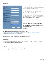
Page 36: ...am 1 s Media Resource Locator MRL Second Stream Enable Disable Stream 2 s Video Audio Second Stream MRL Text field for RTMPS Stream 2 s Media Resource Locator MRL RTSP Settings The RTSP Settings section allows you to enable or disable RTSP Authorization RTSP Auth Enable Disable RTSP authorization ONVIF Settings The ONVIF Settings section allows you to adjust the ONVIF settings of the camera ONVIF ...

Page 37: ...dress field when NDI Discovery server is enabled Enable NDI Multicast Server Enable Disable the NDI Multicast Server NDI Multicast Address Multicast address field when NDI Multicast server is enabled NDI Multicast Mask Used to adjust the NDI Multicast Subnet Mask NDI Multicast TTL Used to adjust the Multicast Time To Live interval NDI Firmware Version Displays the current NDI version on the camera...

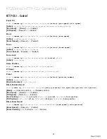
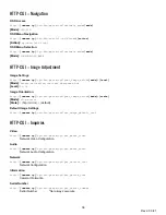
Page 38: ...n lock unlock Home Position http camera ip cgi bin ptzctrl cgi ptzcmd home PT Reset http camera ip cgi bin param cgi pan_tiltdrive_reset Preset http camera ip cgi bin ptzctrl cgi ptzcmd action position number Action posset poscall Position Number 0 89 100 254 Direct Position Recall http camera ip cgi bin ptzctrl cgi ptzcmd mode pan speed tilt speed pan position tilt position Mode abs Absolute posi...

Page 39: ... 0 14 Image Orientation http camera ip cgi bin param cgi post_image_value mode state Mode flip mirror State 1 flip mirror 0 default Default Image Settings http camera ip cgi bin param cgi get_image_default_conf HTTP CGI Inquiries Video http camera ip cgi bin param cgi get_media_video Network Video Configuration Audio http camera ip cgi bin param cgi get_media_audio Network Audio Configuration Netw...

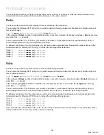
Page 40: ...pg Image 4 http camera ip photo4 jpg Videos You have two 2 options to initiate a series of four 4 videos being captured You can enter the following HTTP string into any web browser on the same network as the camera to initiate a series of four 4 video recordings http camera ip cgi bin booth cgi 0 4 delay video length In this example Delay is utilized to add additional delay in seconds between vide...

Page 41: ...on a steady horizontal and level surface o Check the building and any supporting furniture for vibration Ceiling mounts are often affected by building vibration more than wall mounts o Any external vibration that is affecting the camera will be more apparent when in tele zoom zoomed in settings Control IR Remote controller does not control the camera o Does one of the four 4 Camera Select buttons ...

Page 42: ...o EN 61000 3 3 2013 o EN 55035 2017 RoHS Tested under RoHS Directive 2011 65 EU 2015 863 o IEC 62321 3 1 2013 o IEC 62321 5 2013 o IEC62321 4 2013 AMD1 2017 o IEC 62321 7 1 2015 o IEC 62321 7 2 2017 o IEC 62321 6 2015 o IEC 62321 8 2017 Changelog June 2021 Rev 2 0 Release of User Manual 2 0 NDI HX update to NDI 4 on cameras August 2020 Rev 1 6 Updated warranty information ...

Reviews: