background image

Page 10
Operation

TM-250 Miniature CCD Camera


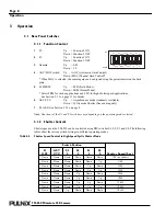
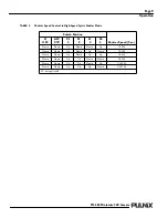
TABLE 3.

Shutter Speed Control in Post-Reset Asynchronous Shutter Mode

Switch Position

Shutter Speed (Sec.)

F1

OFF

ASY

CYC

S3

0

S2

0

S1

0

S0

0

Down

Up

Down

Down

Down

Up

1/60

Down

Up

Down

Down

Up

Down

1/120

Down

Up

Down

Down

Up

Up

1/250

Down

Up

Down

Up

Down

Down

1/500

Down

Up

Down

Up

Down

Up

1/1,000

Down

Up

Down

Up

Up

Down

1/1,600

Down

Up

Down

Up

Up

Up

1/1,800

Down

Up

Up

Down

Down

Down

1/2,100

Down

Up

Up

Down

Down

Up

1/2,400

Down

Up

Up

Down

Up

Down

1/2,800

Down

Up

Up

Down

Up

Up

1/3,500

Down

Up

Up

Up

Down

Down

1/4,400

Down

Up

Up

Up

Down

Up

1/6,200

Down

Up

Up

Up

Up

Down

1/10,200

F2 Up: SYNC signal is continuous.

F2 Down: SYNC signal is available in one field right after VINIT.

TABLE 4.

Shutter Speed Control in Pre-Reset Asynchronous Shutter Mode

Switch Position

Shutter Speed (Sec.)

F1

OFF

ASY

CYC

S3

0

S2

0

S1

0

S0

0

Up

Up

Down

Down

Down

Up

1/29,100

Up

Up

Down

Down

Up

Down

1/10,200

Up

Up

Down

Down

Up

Up

1/6,200

Up

Up

Down

Up

Down

Down

1/4,400

Up

Up

Down

Up

Down

Up

1/3,500

Up

Up

Down

Up

Up

Down

1/2,800

Up

Up

Down

Up

Up

Up

1/2,400

Up

Up

Up

Down

Down

Down

1/2,100

Up

Up

Up

Down

Down

Up

1/1,800

Up

Up

Up

Down

Up

Down

1/1,600

Up

Up

Up

Down

Up

Up

1/1,500

F2 Up: SYNC signal is continuous.

F2 Down: SYNC signal is available in one field right after VINIT.
Summary of Contents for TM-250

Page 1: ...69 0081 Rev A TM 250 Miniature CCD Camera I m a g i n g P r o d u c t s O p e r a t i o n M a n u a l...

Page 2: ...been declared to be in conformance with the applicable EEC Council Direc tives However certain factory installed options or customer requested modifications may compromise electromagnetic com patibili...

Page 3: ...utter Control 8 3 1 3 Field and Frame Modes 11 3 2 External Sync 12 3 2 1 Timing 13 3 2 2 Interfacing to Frame Grabbers 13 3 3 Operating Modes 13 3 3 1 Standard Interlace Mode 14 3 3 2 Cyclic Continuo...

Page 4: ...n Mode 27 5 2 6 Pulse Width Integration Mode 27 6 Troubleshooting 29 6 1 Problems and Solutions 29 6 1 1 Symptom NoVideo 29 6 1 2 Symptom DarkVideo 29 6 1 3 Symptom Non SynchronizedVideo 29 6 1 4 Symp...

Page 5: ...Mode 19 FIGURE 11 High Speed Cyclic Shutter Mode Timing 20 FIGURE 12 Trigger Position Reset Restart Mode Timing 21 FIGURE 13 Trigger Width Reset Restart Shutter Mode Timing 22 FIGURE 14 Strobe Asynchr...

Page 6: ...ntrol in High Speed Cyclic Shutter Mode 18 TABLE 6 Trigger Position Reset Restart Shutter Mode 21 TABLE 7 Trigger Width Reset Restart Shutter Mode 22 TABLE 8 Strobe Asynchronous Shutter Mode 22 TABLE...

Page 7: ...o 1 10 000 1 29 100 in some operating modes in discrete steps via a manually controlled DIP switch on the back panel Miniaturized and lightweight The use of a CCD image sensor in the video camera modu...

Page 8: ...ed by a magnetic field it will produce stable images even when placed next to objects such as electric furnaces welding machines or NMR scanners Quick start up and low power consumption Image capture...

Page 9: ...ion and related applications Other uses include remotely piloted vehicles miniature inspection devices surveillance microscopes and medical equipment 1 5 System Configuration Figure 1 below presents a...

Page 10: ...ponents List below to assure that you have received everything as ordered and that nothing has been overlooked in the packing materials If any item is missing please contact your PULNiX representative...

Page 11: ...supply The PD 12UU power supply can be connected to the PULNiX power cable via a terminal strip or directly When wiring the PD 12 power supply directly please note the following The lead ends must be...

Page 12: ...g Your Own Power Cable Consult the pin out for the camera purchased Connect the Ground and 12V power leads of the PD 12UUP power connector to Pin 1 and Pin 2 respectively power must be DC regulated an...

Page 13: ...clockwise until it firmly seats on the mounting ring Do not force the lens if it does not seat properly Please note that some lenses with extremely long flangebacks may exceed the mounting depth of t...

Page 14: ...g only 7 S3 to S0 See Section 3 1 2 on page 8 Note Functions of the F1 and F2 switches vary depending on the operating mode selected 3 1 2 Shutter Control Shutter speeds on the TM 250 can be controlle...

Page 15: ...p Down 1 3 500 Down Down Up Down Up Up 1 4 400 Down Down Up Up Down Down 1 6 200 Down Down Up Up Down Up 1 10 200 Down Down Up Up Up Down 1 29 100 F2 not applicable TABLE 2 Shutter Speed Control in Hi...

Page 16: ...Down Down 1 4 400 Down Up Up Up Down Up 1 6 200 Down Up Up Up Up Down 1 10 200 F2 Up SYNC signal is continuous F2 Down SYNC signal is available in one field right after VINIT TABLE 4 Shutter Speed Co...

Page 17: ...and equals with frame mode one row at 1 30 sec Since shutter mode is only one field output per shutter and darker than normal image two row binning is effective This mode also reduces interlace moire...

Page 18: ...output video If external vertical drive VD is applied to the camera it may cause the video output to be delayed 1 HD 1 HD 64 0 s If the imaging system is capable of automatically detecting the start o...

Page 19: ...l of the camera Standard Interlace Mode Field integration Mode Frame Integration Mode External Sync Mode Non interlace Mode Cyclic Continuous Shutter Mode Asynchronous Reset and Asynchronous Shutter I...

Page 20: ...hutter and darker than normal image two row binning is effective This mode also reduces interlace moire when a sharp horizontal pattern is observed For higher pixel definition such as gauging and sub...

Page 21: ...evious signal residuals prior to reset A frame grabber has to know which frame or field to capture External HD must be applied for this operation 3 3 6 External Shutter Control The shutter speed or ex...

Page 22: ...timing is created by the edge of external HD the HD must come earlier than VD Some sync generators however produce both VD and HD exactly in phase In this case external factors like jitter or parasiti...

Page 23: ...below illustrates the proper operation with constant 2 line exposure period Figure 8 on the other hand illustrates the illegal operation where the exposure time varies by the position of TRIG Shutter...

Page 24: ...called electronic shutter Since the discharge pulse is not employed in this mode we refer this mode to NO shutter TABLE 5 Shutter Speed Control in High Speed Cyclic Shutter Mode F1 OFF ASY CYC S3 0 S...

Page 25: ...ally carries out the internal shutter operation The discharge and transfer repeats in every field at a predefined timing The discharge occurs in every line and stops at the defined timing in one field...

Page 26: ...s to synchronize with Reset Restart EXT VD pulse It should be 2 lines or more in width The leading edge of TRIG pulse produces DSUB discharge pulse and starts the exposure The transfer read out occurs...

Page 27: ...er pulse and resume after the 11th line Because V shift has been halted part of the field cannot be shifted out To get a full picture field the next shutter trigger must be prohibited which means a fu...

Page 28: ...occur in this mode so that the strobe must engage after VINIT pulse implied but before transfer occurs at 11th line for TM 250 and at 16th line for TM 260 When the F2 switch is Up ON in Frame storage...

Page 29: ...s damped Different from Pre reset Mode the internal counter reset takes place when predefined exposure time has passed after the discharge The photo transfer occurs at the first line of the odd field...

Page 30: ...Down Up Down Up Down Up Negative 1 1 000 Down Up Down Up Up Down Negative 1 1 600 Down Up Down Up Up Up Negative 1 1 800 Down Up Up Down Down Down Negative 1 2 100 Down Up Up Down Down Up Negative 1 2...

Page 31: ...chronous Shutter Mode The purpose of this mode of operation is to maintain compatibility with the TM 7 6 and the TM 200 300 series cameras This shutter operation enables image capture at extremely hig...

Page 32: ...does in high speed cyclic shutter mode F1 OFF ASY CYC S3 0 S2 0 S1 0 S0 0 TRIGGER Polarity Exposure Time sec Up Up Up Down Down Down Up Negative 1 29 100 Up Up Up Down Down Up Down Negative 1 10 200 U...

Page 33: ...xposure time to be longer than one field and also works for strobe application The camera operates in the same way as it does in Async Pulse Width Mode Shutter When VINIT is high train of discharge pu...

Page 34: ...Integration Mode F1 OFF ASY CYC S3 0 S2 0 S1 0 S0 0 TRIGGER Polarity Up Up Up Up Up Up Negative F2 Up SYNC signal is continuous F2 Down SYNC signal is available in the two fields Frame mode and in one...

Page 35: ...Shutter control Async mode Lens 6 1 2 Symptom Dark Video Remedies Check that the following are properly connected and operational Shutter selection Iris opening on the lens 6 1 3 Symptom Non Synchroni...

Page 36: ...ources For further information and support Phone 408 747 0300 800 445 5444 800 3 PULNIX 24 hour message access Fax 408 747 0660 E mail imaging jaipulnix com Mail PULNiX America Inc Sales Department 13...

Page 37: ...tion 0 5 lux F 1 4 Video output 1 0 Vp p composite video 75 AGC ON OFF back panel selectable Gamma 1 or 0 45 back panel selectable Lens mount C mount Power requirement 190 mA 11 15V Operating temp 10...

Page 38: ...ons SECURE HATCH IN PLACE AFTER FINAL ADJUSTMENTS 44 0 1 73 18 0 0 71 13 0 0 51 49 9 1 96 62 6 2 46 44 0 1 73 POWER VIDEO GAIN 8X M3 X 5 0 0 20 DEEP 20 5 0 81 16 5 0 65 13 0 0 51 18 0 0 71 1 4 20 93 4...

Page 39: ...room for the stripe filter incorporated in the color camera Additionally the shorter flange back length allows for reduction of the effective diameter of the first lens and reduces the number of lens...

Page 40: ...FIGURE 22 Front End Detail 7 2 Spectral Response FIGURE 23 Spectral Response TM 250 FRONT END 18 11 0 713 FILTER IMAGER P W B ICX038DLA IMAGER GASKET 400 500 600 700 800 900 1000 1100 1200 0 0 2 0 1...

Page 41: ...PULNiX Inc 1330 Orleans Drive Sunnyvale CA 94089 Tel 408 747 0300 Tel 800 445 5444 Fax 408 747 0660 w w w j a i p u l n i x c o m I m a g i n g P r o d u c t s 69 0081 Rev A Email imaging jaipulnix c...

Reviews: