Page 13
Operation
TM-250 Miniature CCD Camera
3.2.1
Timing
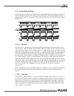
FIGURE 4.
TM-250 Timing Chart
3.2.2
Interfacing to Frame Grabbers
The TM-250 camera can be connected to a frame grabber using either the 12-pin connector or the BNC
connector on the rear panel of the camera.
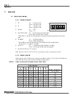
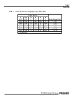
3.3 Operating Modes
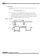
Besides normal operation, the TM-250 supports the following versatile operations that can be selected
by the DIP switch on the rear panel of the camera:
•
Standard Interlace Mode
Field integration Mode
Frame Integration Mode
•
External Sync Mode
•
Non-interlace Mode
•
Cyclic (Continuous) Shutter Mode
•
Asynchronous Reset and Asynchronous Shutter
Image sensing period
Optical
black period
Dummy
H register
H register
stop period
Optical
black period
CCD photo sensors
allocation
CCD output
signal
Effective picture
period
HD
6.36
µ
Sec
91
40
77
22
3
819
768
40
154
H BLK 10.76
µ
Sec
21
1.47
µ
Sec
70
H SYNC
4.89
µ
Sec
Composite video
output
B1
B2
B3
1
2
3
4
5
6
7
8
9
10
757
758
759
760
761
762
763
764
765
766
767
768
B1
B40
B1
D1
D22
910
63.56
µ
Sec (1 horizontal line)
B40
CBRK


