CT10.241, CT10.241-C1
CT-Series
3-P
HASE
,
24V,
10A,
240W
May 2018 / Rev. 2.0a DS-CT10.241-EN All values are typical figures specified at 3x 400Vac, 50Hz input voltage, symmetrical
phase voltages, 24V, 10A output load, 25°C ambient and after a 5 minutes run-in time unless otherwise noted.
www.pulspower.com Phone +49 89 9278 0 Germany
10/28
9.
F
UNCTIONAL
D
IAGRAM
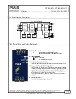
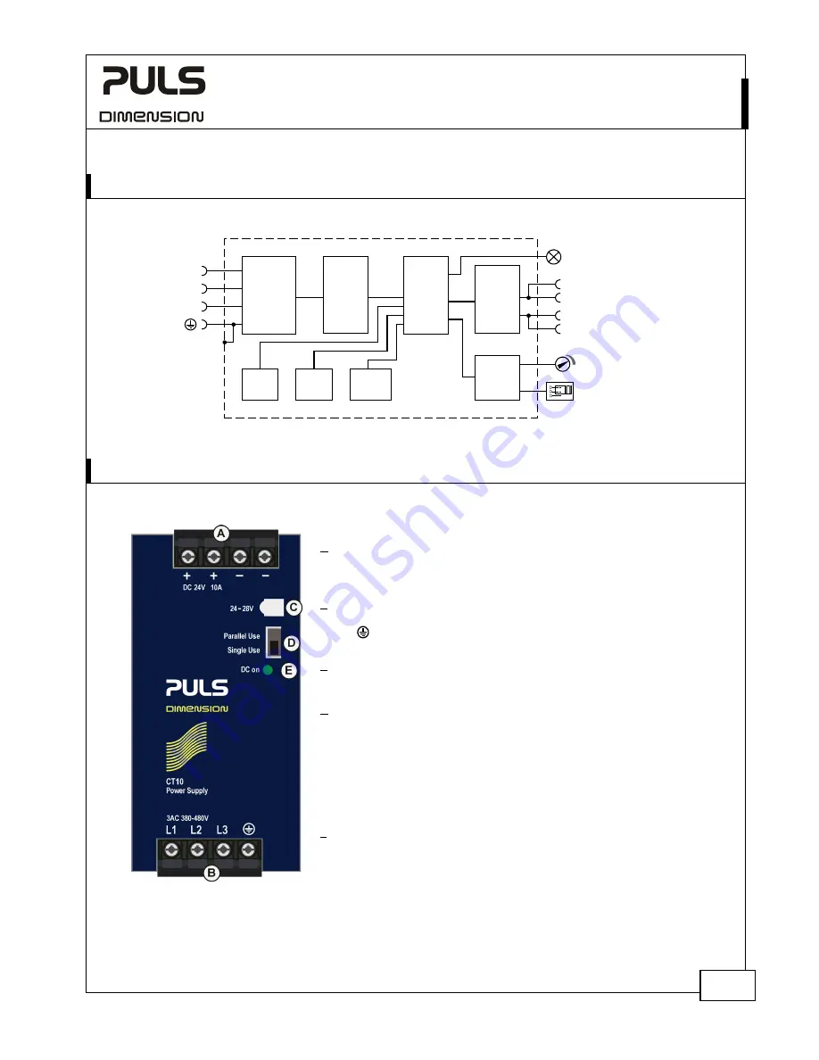
Fig. 9-1
Functional diagram
+
+
-
-
V
OUT
Output
Over-
Voltage
Protection
PFC
Inductor
Inrush
Limiter
Transient
Filter
Input Fuses
Input Filter
Input
Rectifier
Output
Voltage
Regulator
Power
Converter
Output
Filter
Output
Power
Manager
Temper-
ature
Shut-
down
DC-ok
LED
L2
L3
L1
Single /
Parallel
10.
F
RONT
S
IDE AND
U
SER
E
LEMENTS
Fig. 10-1
Front side
A Output Terminals
+
Positive output (two ide poles)
–
Negative/ return output (two identical - poles)
B Input Terminals
L1, L2, L3
Line input
PE (Protective Earth) input
C Output voltage potentiometer
Open the flap to adjust the output voltage. The factory setting is 24.1V
D Jumper for “Parallel Use” “Single Use”
Set the jumper to “Parallel Use” when devices are connected in parallel
to increase the output power. In order to achieve a sharing of the load
current between the individual power supplies, the “Parallel Use”
regulates the output voltage in such a manner that the voltage at no
load is approx. 4% higher than at nominal load.
A missing jumper equals “Single Use” mode, which is also the factory
setting.
E DC-OK LED
(green)
On, when the output voltage is above 21V.

