background image

www.pulsar.pl


BNC04124 


G

REEN POWER CCTV BNC


- TAMPER output indicating enclosure opening 

- microswitch, NC contacts (enclosure closed), 
0,5A@50V DC (max.) 

Optical indication of operation: 

YES – LED lights 

Technical outputs: 
- FPS technical output indicating output fuse 
activation 


- OC type, 50mA max.  
Normal operation:  L state (0V),  
failure: H state (hi-Z), (automatic return once the normal 
operation is restored) 
- relay type: 1A@ 30VDC/50VAC, delay time: 
approximately 10 seconds 

F1 ÷ F4 fuses 

F 1A or PTC 1,1A 

      Mechanical parameters (Table 4). 

Enclosure dimensions 

230 x 281 x 116  mm (WxHxD) 

Mounting 

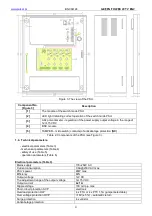
See Figure 3 

Net weight 

2,85kg / 3,04kg 

Enclosure 

DC01 steel plate, 1,0mm, RAL 9003 

Closing 

Cylindrical screw x 1 (at the front) lock assembly possible 

Terminals 

Switch mode power supply: 

Φ

0,63-2,5 (AWG 22-10) 

BNC module : 

Φ

0,5-2,1 (AWG 24-12) 

Input / output of the video signal: BNC 
TAMPER output: 

Φ

0,8. 

Notes 

The enclosure has a 15mm distance from the mounting surface so the cables 
can be led.  

          Safety of use (Table 5). 

Protection class PN-EN 60950-1:2004 

I (first) 

Protection grade PN-EN 60529: 2002 (U) 

IP20 

Insulation electrical strength: 
- between input (network) circuit and the output circuits of the PSU  
(I/P-O/P) 
- between input circuit and PE protection circuit  (I/P-FG) 
- between output circuit and PE protection circuit (O/P-FG) 


3000 V/AC min. 
1500 V/AC min. 
  500 V/AC min. 

Insulation resistance: 
- between input circuit and output or protection circuit 

 
100 M

, 500V/DC  

Operation parameters (Table 6). 

Operating temperature 

-10ºC...+40ºC (see Figure1) 

Storing temperature 

-20ºC...+60ºC 

Relative humidity  

20%...90%, no condensation 

Vibrations during operation  

unacceptable 

Surges during operation 

unacceptable 

Direct insolation 

unacceptable 

Vibrations and surges during transport 

According 

to 

the 

PN-83/T-42106 

standard 

 
2.  Installation. 


2.1. Requirements. 


The  buffer  PSU  should  be  mounted  by  a  qualified  installer,  holding  relevant  permits  and  licenses 

(applicable and  required  for  a  given  country)  for  230V/AC  and  low-voltage  installations. The  unit  should  be 
mounted  in  confined  spaces,  in  accordance  with  the  2nd environmental  class,  with  normal  relative  humidity 
(RH=90% maximum, no condensation) and temperature range from -10°C up to +40°C. The  power  supply  sh ould  
operate  in  a  vertical position in order to provide free and  convectional  air  flow  through ventilating holes of the 
enclosure.  

 
During normal operation, the total current drawn by the device should not exceed 
 I =   4x1A.  

The  power  supply  is  designed  for  a  continuous  operation  and  is  not  equipped  with  a 

power-switch.  Therefore,  an  appropriate  overload  protection  in  the  power  supply  circuit  should  be  provided. 
Moreover, the user should be informed how to disconnect the power supply unit from the mains supply (usually by 

Summary of Contents for GREEN POWER CCTV BNC04124

Page 1: ...BNC04124 v 1 0 BNC 12V 4x1A Switch mode power supply unit for CCTV EN Edition 1 from 26 11 2013 Supersedes the edition BNC GREEN POWER CCTV ...

Page 2: ...puts 4 Service and operation 4 1 Overload or short circuit of the power supply output 4 2 Maintenance 1 Technical description 1 1 General description The PSU BNC04124 is intended for uninterrupted supply of CCTV systems requiring stabilized voltage of 12V DC The output voltage can be adjusted with a potentiometer between 12V and 15V DC The power supply unit enables transmitting power and video usi...

Page 3: ...cuits 4 Jumper to select melting fuse or PTC polymer fuse 5 Green LED L1 L4 voltage indication at the AUX outputs during normal operation these LEDs are on 6 BNC connector of the video output to the DVR 7 BNC connector of the video input from the cameras 8 AUX1 AUX4 camera power supply outputs 12 15V 9 FPS technical output indicating failure OC type 10 FPS technical output indicating failure relay...

Page 4: ... Figure 3 1 4 Technical parameters electrical parameters Table 3 mechanical parameters Table 4 safety of use Table 5 operation parameters Table 6 Electrical parameters Table 3 Mains supply 176 264V AC Current consumption 0 6A 230V AC max PSU s power 48W max Efficiency 80 Output voltage 12V DC The adjustment range of the output voltage 12 15V DC Output current 4x 1 A Ripple voltage 100 mV p p max S...

Page 5: ...E protection circuit O P FG 3000 V AC min 1500 V AC min 500 V AC min Insulation resistance between input circuit and output or protection circuit 100 MΩ 500V DC Operation parameters Table 6 Operating temperature 10ºC 40ºC see Figure1 Storing temperature 20ºC 60ºC Relative humidity 20 90 no condensation Vibrations during operation unacceptable Surges during operation unacceptable Direct insolation ...

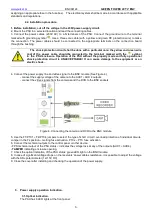
Page 6: ...ircuit is UNACCEPTABLE It can cause damage to the equipment or an electric shock 4 Connect the power supply line and video signal to the BNC module See Figure 4 connect the supply voltage of the camera to the AUX1 AUX 4 outputs connect the video signals from the cameras and the DVR to the BNC sockets Figure 4 Connecting the camera and DVR to the BNC module 5 Use the F1 PTC1 F4 PTC4 jumpers to sele...

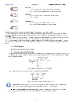
Page 7: ...re 2 component 5 indicate voltage at the individual outputs of the module L1 for AUX 1 etc Activation of the short circuit overload protection of a given circuit is indicated by turning off one of the Lx LEDs 3 2 Technical outputs The PSU has the following indication outputs FPS technical output of the PSU status OC type output indicating failure short circuit overload During normal operation shor...

Page 8: ...rer 4 The warranty applies to complete equipment accompanied by a properly filled warranty claim with a description of the defect 5 Should the claim be accepted the manufacturer is obliged to provide warranty repairs at the earliest convenience however not later that within 14 days from the delivery to the service centre of the manufacturer 6 The repair period mentioned in point 5 may be prolonged...

Reviews: