background image

www.pulsar.pl                                                          HPSB2524B                                                      

GREEN POWER


5


W

H

D

LED indication:  
- AC diode indicating AC power status 
- AUX diode indicating DC power status at 
the PSU output 

 
- red, normal status 

– on, failure: off 

- green, normal status 

– on, failure: off  

 
   Mechanical parameters (tab. 4) 

Enclosure dimensions 

280 x 292 x 80 + 8  [mm] (WxHxD) 

Fixation 

See figure 2 

Fitting battery 

2x7Ah/12V (SLA) max. 
180x155x75mm (WxHxD) max  

Net/gross weight 

2,1 / 2,3 kg 

Enclosure  

Steel plate DC01, thickness: 0,7mm, colour: RAL 9003 

Closing 

Cheese screw x 2 (at the front),  (lock assembly possible) 

Connectors 

Power-supply: 

Φ0,63-2,50 (AWG 22-10) 

Outputs : Φ0,63-2,50 (AWG 22-10) 
Battery output BAT: 6,3F-2,5  
TAMPER output: wires  

Notes 

The enclosure does not touch the assembly surface so that cables can be led. 
Convectional cooling. 


Operation safety (tab.5) 

Protection class EN 60950-1:2007 

I (first) 

Protection grade EN 60529: 2002 (U) 

IP20 

Electrical strength of insulation: 
- between input and output circuits of the PSU (I/P-O/P) 
- between input circuit and PE protection circuit (I/P-FG) 
- between output circuit and PE protection circuit (O/P-FG) 

 
3000 V/AC min. 
1500 V/AC min. 
  500 V/AC min. 

Insulation resistance: 
- between input circuit and output or protection circuit 

 
100 MΩ, 500V/DC 


    Operating

 parameters (tab.6) 

Environmental class 

II 

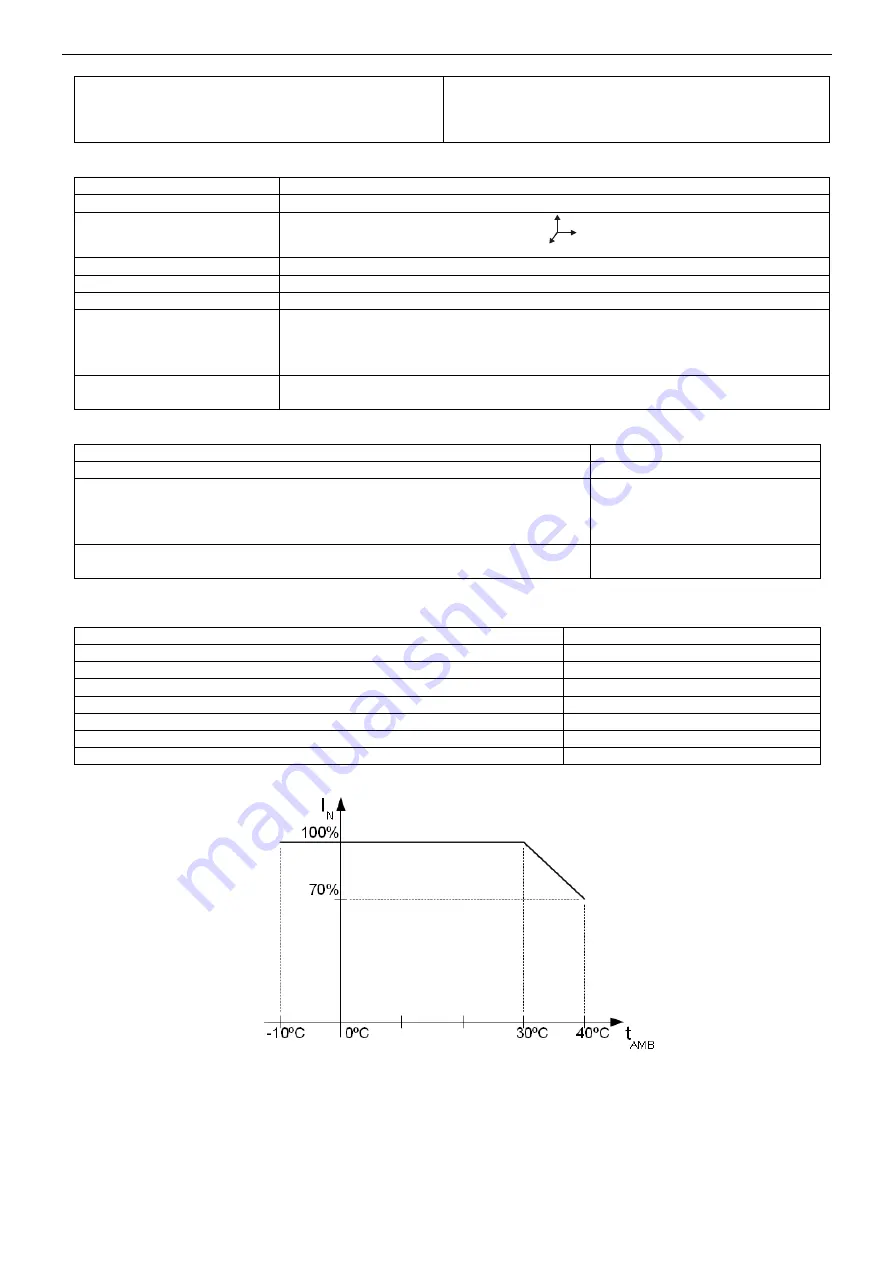
Operating temperature 

-

10ºC...+40ºC (see: chart 1) 

Storage temperature 

-

20ºC...+60ºC 

Relative humidity 

20%...90%, without condensation 

Vibrations during operation 

unacceptable 

Impulse waves during operation 

unacceptable 

Direct insulation 

unacceptable 

Vibrations and impulse waves during transport 

According to PN-83/T-42106 


Chart 1. Acceptable output current from the PSU depending on ambient temperature. 


Summary of Contents for Green Power HPSB 2524B

Page 1: ...HPSB 2524B v 1 0 HPSB 27 6V 2 2A 2x7Ah Buffer switch mode power supply unit EN Edition 1 from 30 09 2014 Supersedes the edition ...

Page 2: ...at require stabilised voltage of 24V DC 15 The PSU provides voltage of U 27 6V DC with output current of I 2 2A 0 3A for battery charge In case of power decay a battery back up is activated immediately The PSU is constructed based on the switch mode PSU with high energy efficiency The PSU is housed in a metal enclosure colour RAL 9003 which can accommodate two 7Ah 12V batteries A micro switch indi...

Page 3: ...e tab 2 3 green LED indicates AC power 4 potentiometer output voltage adjustment 5 BAT GND battery outputs BAT red GND black 6 TAMPER contact sabotage protection NC 7 Additional connector for LED indication Tab 1 The elements of the PSU Element Fig 2 Description L N L N power supply connector PE PE Protection connector electric shock protection V V DC supply output DC supply output GND Tab 2 Outpu...

Page 4: ...y charge refer to chart 1 Output current tAMB 40 C 1 45A 0 3A battery charge refer to chart 1 Voltage adjustment range 24 28V DC Ripple 120mV p p max Current consumption by PSU systems 75 mA Battery charge current 0 3A max 2x 7Ah 5 Short circuit protection SCP electronic Overload protection OLP U 105 150 of power supply automatic return Battery circuit protection SCP and reverse polarity connectio...

Page 5: ...ables can be led Convectional cooling Operation safety tab 5 Protection class EN 60950 1 2007 I first Protection grade EN 60529 2002 U IP20 Electrical strength of insulation between input and output circuits of the PSU I P O P between input circuit and PE protection circuit I P FG between output circuit and PE protection circuit O P FG 3000 V AC min 1500 V AC min 500 V AC min Insulation resistance...

Page 6: ...andards and regulations 2 2 Installation procedure 1 Before installation cut off the voltage in the 230V power supply circuit 2 Mount the PSU in a selected location and connect the wires 3 Connect the power cables 230Vac to L N clips of the PSU Connect the ground wire to the clip marked by the earth symbol PE PSU module connector Use a three core cable with a yellow and green PE protection wire to...

Page 7: ...he restoration of the voltage takes place immediately after the failure overload is over 4 2 Disconnection of discharged battery The PSU is equipped with the discharged battery disconnection system During the battery assisted operation reducing voltage below 19V at the battery terminals will cause battery disconnection 4 3 Maintenance Any and all maintenance operations may be performed following t...

Page 8: ...ter that within 14 days from the delivery to the service centre of the manufacturer 6 The repair period mentioned in item 5 may be prolonged if there are no technical possibilities to carry out the repairs or if the equipment has been conditionally accepted due to the breaking warranty terms by the claimant 7 All the services rendered by force of the warranty are carried out at the service centre ...

Reviews: