background image

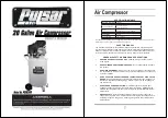
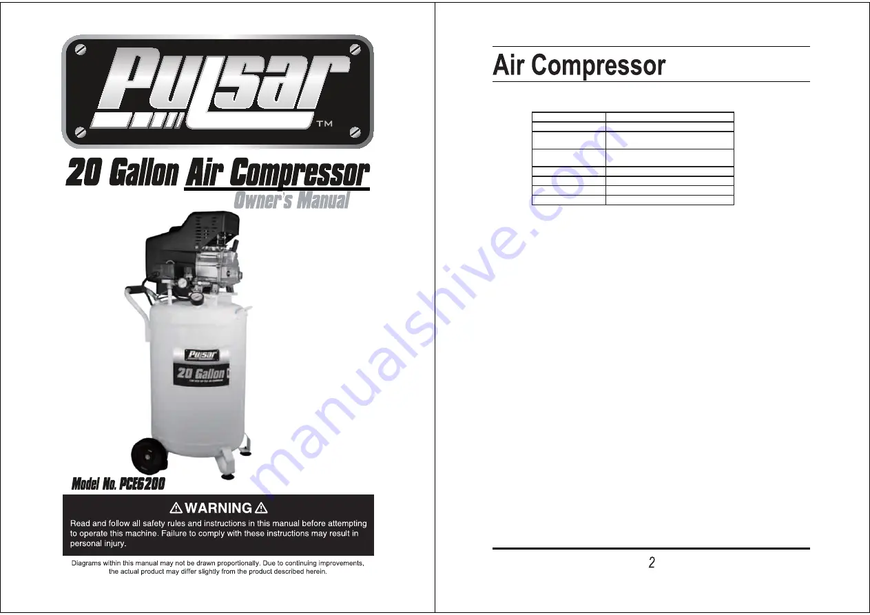
SPECIFICATIONS TABLE

Maximum Air Pressure

115 PSI

Air Tank Capacity

20 Gallons

Air Flow Capacity

6.2 CFM at 40 PSI
5.2 CFM at 90 PSI

Motor

2.5 HP Working /  4 HP Peak
120 Volt / 60 Hz / 13 A / 1-Phase

Required Circuit

Minimum 20 Amp *

Dedicated

Pump Stage

Single

Air Outlet Size

1/4” - 18 NPT

Accessories

Air Intake Filter;  Air Hose Coupler

*A dedicated circuit is used only for a single load, for this compressor.  Other loads on the circuit must be 
disconnected or turned off when the compressor is plugged in.

SAVE THIS MANUAL

You will need this manual for the safety warnings and precautions, assembly, operat-
ing, inspection, maintenance and cleaning procedures, parts list and assembly diagram.
Keep your invoice with this manual. Write the invoice number on the inside of the front 
cover.  Keep this manual and invoice in a safe and dry place for future reference.

GENERAL SAFETY WARNINGS AND PRECAUTIONS

1.

KEEP WORK AREA CLEAN AND DRY.

Cluttered, damp, or wet work areas

invite injuries.

2.

KEEP CHILDREN AWAY FROM WORK AREA.

Do not allow children to handle

this product.

3.

KEEP IDLE EQUIPMENT.

When not in use, tools and equipment should be kept

in a dry location to inhibit rust.  Always lock up tools and equipment, and keep out
of reach of children.

4.

DO NOT USE THIS PRODUCT IF UNDER THE INFLUENCE OF ALCOHOL OR
DRUGS.

Read warning labels on prescriptions to determine if your judgement or

UHÀH[HVDUHLPSDLUHGZKLOHWDNLQJGUXJV,IWKHUHLVDQ\GRXEWGRQRWDWWHPSWWR

use this product.

5.

USE EYE AND HAND PROTECTION.

Wear ANSI-approved safety impact

goggles and heavy-duty work gloves when using this product.  ANSI-approved
safety impact eyeglasses and heavy-duty work gloves are available from Harbor
Freight Tools.

6.

DRESS SAFELY.

Do not wear loose clothing or jewelry, as they can become

caught in moving parts. Wear a protective hair covering to prevent long hair from
becoming caught in moving parts.  If wearing a long-sleeve shirt, roll sleeves up
above elbows.

Summary of Contents for PCE6200

Page 1: ...NGS AND PRECAUTIONS 1 KEEP WORK AREA CLEAN AND DRY Cluttered damp or wet work areas invite injuries 2 KEEP CHILDREN AWAY FROM WORK AREA Do not allow children to handle this product 3 KEEP IDLE EQUIPMENT When not in use tools and equipment should be kept in a dry location to inhibit rust Always lock up tools and equipment and keep out of reach of children 4 DO NOT USE THIS PRODUCT IF UNDER THE INFL...

Page 2: ...SUHPLXP TXDOLWy ZHLJKW QRQ GHWHUJHQW FRPSUHVVRU RLO EHIRUH HDFK XVH 5XQQLQJ WKH Air Com SUHVVRU ZLWK QR RLO RU ORZ RLO ZLOO FDXVH GDPDJH WR WKH HTXLSPHQW Note 7KH RLO UHVHUYRLU KDV DQ RSWLPDO FDSDFLW RI RXQFHV RI RLO 2 WHEN CHECKING THE OIL LEVEL Make sure to unscrew GR QRW SXOO WKH UHDWKHU VDOYH RXW See Figure C and Assy Diagram B 3 MAKE SURE ALL TOOLS AND EQUIPMENT USED WITH THE AIR COM PRESSOR ...

Page 3: ...l the level of oil reaches the maximum level as indicated on the Oil Window 20B The optimal capacity of the oil reservoir is 30 ounces R QRW RYHU OO Then thread the Breather Valve back into the Oil Fill Hole being careful not to strip the plastic threads See Figure C and Assy Diagram B To Turn The Air Compressor On 1 Check to make sure the Water Drain Valve 10A is fully closed 2 Turn the Air Flow ...

Page 4: ...threads the Water Drain Valve 10A until the compressed air and condensation begins to be released from the Air Tank 9A Allow VXI FLHQW time for all of the air and condensation to escape from the Air Tank 7KHQ UPO UHWLJKWHQ WKH Water Drain Valve 7 INSPECTION MAINTENANCE AND CLEANING 1 CAUTION Always disconnect the Air Compressor from its electrical supply source before performing any inspection mai...

Page 5: ...y and are not avail able individually as replacement parts PARTS LIST B ASSEMBLY DIAGRAM B Part Description Qty 1B Bolt 4 2B Cylinder Case 1 3B Gasket 1 4B Valve Seat 1 5B Gasket 1 6B Cylinder 1 7B Compression Ring 2 8B Oil Scraping Ring 1 9B Piston 1 10B Gasket 1 11B Piston Pin 1 12B End Cover 1 13B Crankshaft Retainer 2 14B Breather Valve 1 15B Connecting Rod 1 16B Gasket 1 17B Bolt 6 18B Front ...

Page 6: ...Air compressors with 60 and 80 gallon tanks will be inspected at the site of installation Contact the nearest Authorized Warranty Service Center that provides on site service calls for service call arrangements If the purchaser does not receive satisfactory results from the Authorized Warranty Service Center the purchaser should contact Pulsar Products Inc 11 LIMITED WARRANTY cont d THIS WARRANTY ...

Reviews: