8.
NOTE:
With the Air Compressor turned on, the operation is automatic and under
the control of the automatic switches inside the box under the Power Switch (1A).
NEVER open the power switch box or adjust the controls within.
To Adjust The Air Output To The Pneumatic Tool:
1.
NOTE:
When adjusting the air pressure being forwarded to the pneumatic tool,
you will need to compare the pressure readings of both the Tank Pressure Gauge
(3A) and the Tool Pressure Gauge (4A). The reading on the Tank Pressure Gauge
dictates the maximum/minimum air pressure at which the Tool Pressure Gauge may
also be set.
2.
With the Air Compressor running, and the air hose and pneumatic tool hooked up
to the Air Compressor, pull up on the Tool Pressure Adjuster (2A). Turn the Tool
Pressure Adjuster
clockwise to increase
the air output to the tool, up to the work-
ing air pressure (115 PSI) as indicated on the Tank Pressure Gauge (3A).
3.
Turn the Tool Pressure Adjuster (2A)
counterclockwise to decrease
the air output
to the tool, down to the minimum rated pressure (0 PSI) as indicated on the Tank
Pressure Gauge (3A).
To Use The Tank Pressure Relief Valve:
1.
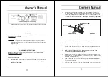
The Tank Pressure Relief Valve Ring (5A) is used when decompression is needed
TXLFNO\DQGHI¿FLHQWO
y.
2.
To decompress the Air Tank (9A) pressure, rotate the “ON/OFF” Power Switch (1A)
up to the vertical position to turn off the Air Compressor.
3.
Pull out on the Tank Pressure Relief Valve Ring (5A) to immediately release air
pressure in the Air Tank (9A).
To Empty Air And Condensation From The Tank:
1.
The Water Drain Valve (10A) is located underneath the Air Tank (9A), and should
be used daily to release all trapped moisture through this valve. The Water Drain
Valve will also eliminate condensation that may cause Air Tank corrosion.
2.
WARNING: Do not open the Water Drain Valve (10A) so that more than four
threads are showing.
3.
Rotate the “ON/OFF” Power Switch (1A) up to the vertical position to turn off the Air
Compressor. Then, unplug the Air Compressor’s Power Cord from the electrical
outlet.
4.
Slowly and carefully unscrew (no more than four threads) the Water Drain Valve
(10A) until the compressed air and condensation begins to be released from the Air
Tank (9A). Allow
VXI¿FLHQW
time for all of the air and condensation to escape from
the Air Tank.
7KHQ¿UPO\UHWLJKWHQWKH
Water Drain Valve.
7
INSPECTION, MAINTENANCE, AND CLEANING
1.
CAUTION:
Always disconnect the Air Compressor from its electrical supply source
before performing any inspection, maintenance, or cleaning.
2.
BEFORE EACH USE,
inspect the general condition of the Air Compressor. Check
all air
¿WWLQJV
for leaks. Check for loose screws, misalignment or binding of moving
parts, cracked or broken parts, damaged power cord and plug, and any other con-
dition that may affect the safe operation of this tool. If abnormal noise or vibration
occurs, immediately disconnect the Air Compressor from its electrical supply source
and have the problem corrected before further use.
Do not use damaged equipment.
3.
DAILY:
Check the Air Compressor oil level. If necessary,
¿OO
with a premium qual-
ity, 30-weight, non-detergent compressor oil.
NOTE:
When checking the oil level,
make sure to
unscrew
(do not pull) the Breather Valve (14B).
4.
DAILY:
Purge the Air Tank (9A) of all air and moisture to prevent corrosion. To do
so, slowly and carefully unscrew (no more than four threads) the Water Drain Valve
(10A) until the compressed air and condensation begins to be released from the Air
Tank. Allow
VXI¿FLHQW
time for all of the air and condensation to escape from the Air
Tank.
7KHQ¿UPO\UHWLJKWHQWKH
Water Drain Valve.
5.
EVERY 100 HOURS OF USE:
Clean the Air Filter (7A) with a mild solvent. Then,
dry and reattach the Air Filter.
NOTE:
Replace the Air Filter if it is too dirty to prop-
erly clean.
6.
EVERY 500 HOURS OR 12 MONTHS:
Replace the old oil with new, premium qual-
ity, 30-weight, non-detergent compressor oil.
7.
TO CLEAN
: wipe with a damp cloth, using a mild detergent or mild solvent.
8.
WHEN STORING
: Keep the Air Compressor in a clean, dry location.
Reference: Overload Switch (35B)
The overload breaker will trip if an over-current condition is sensed, stopping the
motor. If this occurs, shut off the pressure switch and wait at least 5 minutes.
Release the air pressure in the tank to ease restarting. Then press the breaker
button to reset it, and turn on the pressure switch.
8

