www.pulsar.pl
PSBS10A12E
3
4. Buffer power supply unit PSBS 13,8V/8x1A/65Ah
- PSBS 2xLB4 8x1A (AWZ575 or AWZ576) + 65Ah
5. Buffer power supply unit PSBS 13,8V/2x12V/2x5A/65Ah
- PSBS 2xRN500 (13,8V/12V) + 65Ah
6. Buffer power supply unit PSBS 13,8V/2x12V/16x0,5A/65Ah
- PSBS 2xRN500 (13,8V/12V) + 2xLB8 16x0,5A (AWZ578 or AWZ580) + 65Ah
7. Buffer power supply unit PSBS 13,8V/2x12V/10x1A/65Ah
- PSBS 2xRN500 (13,8V/12V) + 2xLB8 10x1A (AWZ579 or AWZ580) + 65Ah
8. Buffer power supply unit PSBS 13,8V/2x12V/8x1A/65Ah
- PSBS 2xRN500 (13,8V/12V) + 2xLB4 8x1A (AWZ575 or AWZ576) + 65Ah
9. Buffer power supply unit PSBS 13,8V/4x5V÷7,4V/4x2A/65Ah
- PSBS 4xDCDC20 (5V÷7,4V/4x2A) + 65Ah
10. Buffer power supply unit PSBS 13,8V/3x5V÷7,4V/12x0,5A/65Ah
- PSBS 3xDCDC20 (5V÷7,4V/2A) + 3xLB4 12x0,5A (AWZ574 or AWZ576) + 65Ah
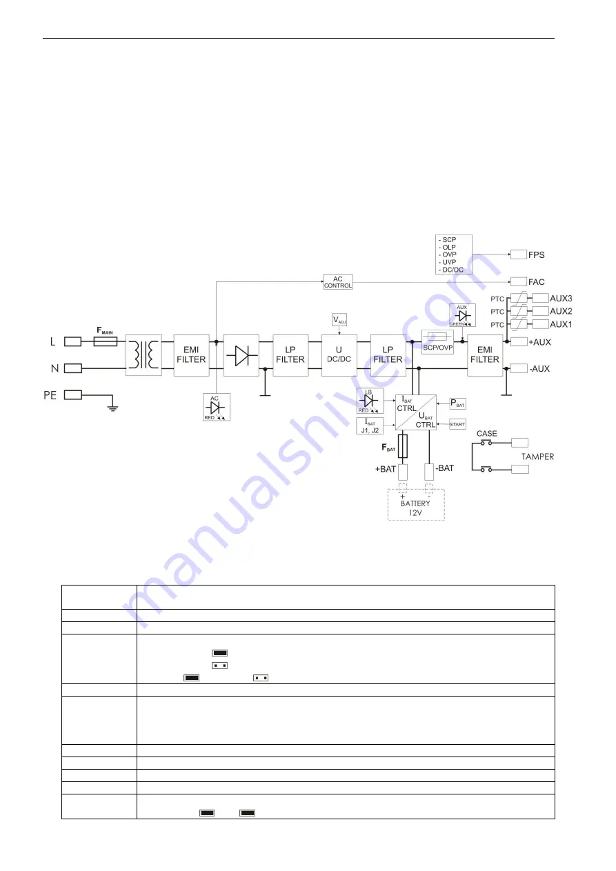
1.2. Block diagram (fig.1).
Fig.1. Block diagram of the PSU.
1.3 Description of PSU components and connectors (tab.1, tab.2, fig.2, fig.3).
Table 1.
Element no.
[Fig. 2]
Description
[1]
F
BAT
fuse in the battery circuit
[2]
START
button (launching the PSU from a battery)
[3]
P
BAT
; pin
configuration of the battery protection system UVP
P
BAT
=
battery protection off
P
BAT
=
battery protection on
Caption:
jumper on,
jumper off
[4]
V
ADJ
potentiometer, DC power adjustment
[5]
+AUX-
+AUX1-
+AUX2-
+AUX3-
DC power outputs (+AUX= +U, -AUX=GND)
[6]
O1, O2, O3, AUX –
LED indication of the PSU status
[7]
AC
- LED indicating presence of AC voltage
[8]
LB
- LED indicating battery charge
[9]
OVP -
LED indicating activation of the over voltage protection OVP
[10]
I
BAT
(J1, J2); pins
- battery charging current adjustment
J1=
J2=
Ibat =0,7A


