RSFUPS108
RACK POWER
5
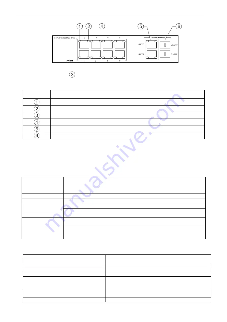
Fig.5. The view of the switch.
Table 2. (See Fig. 5).
Element no.
[Fig. 2]
Description
LINK
- yellow LED - indicating the LAN connection status
PoE
- green LED indicating voltage at the PoE port
PWR
– green LED indicating the supply voltage of the Switch
PoE
port
1÷8
for cameras IP connection (data + power supply)
2 x
UPLINK
ports (G1/TP, G2/TP)
2 x
UPLINK
ports (G1/SFP, G2/SFP)
1.4. Specifications.
- parameters of the switch (tab.3)
- electrical parameters (tab.4)
- mechanical parameters (tab.5)
- operation safety (tab.6)
- operating parameters (tab.7)
Parameters of the switch (tab. 3).
Ports
8 x PoE (10/100Mb/s) (RJ-45)
2 x UPLINK (10/100/1000Mb/s) (RJ-45)
2 x UPLINK (10/100/1000Mb/s) (SFP)
with connection speed auto-negotiation and MDI/MDIX Auto Cross)
PoE power supply
IEEE 802.3af (1
÷8 ports), 48VDC / 15,4W at each port *
Protocols, Standards
IEEE802.3, 802.3u, 802.3x CSMA/CD, TCP/IP
Forwarding rate
10BASE-T: 14880pps/port
100BASE-TX: 148800pps/port
Bandwidth
1,6Gbps
Transmission
method
Store-and-Forward
Optical indication of
operation
Switch power supply;
Link/Act;
PoE Status
*
The given value of 15,4W per port is the maximum value. The total power consumption should not exceed 96W when all PoE ports are
being used.
Electrical parameters (tab. 4).
Mains supply
230V AC (-15%/+10%) 50Hz
Current up to
1,1A max./230V AC
Supply power
110W max.
Output voltage at the PoE ports
48V DC
– maintained regardless of the state of battery charge
The output current at the PoE ports
8 x 0,3A Ʃ=2A (max.)
Battery charge current
(batteries 2x7Ah / 2x17Ah, connect batteries in
series)
0,5A max. (+/-5%)
Short-circuit protection SCP and overload
protection OLP
105% ÷ 150% of the PSU power, manual restart (failure
requires the disconnection of the DC output)
PSU current consumption
200mA/27,6V


