background image

www.pulsar.pl


ROUPS12VR   


RACK POWER CCTV 


As the PSU is designed for a continuous operation and is not equipped with a power-switch, therefore an 

appropriate  overload  protection  shall  be  guaranteed  in  the  power  supply  circuit.  Moreover,  the  user  shall  be 
informed  about  the  method  of  unplugging  (usually  through  assigning  an  appropriate  fuse  in  the  fuse-box).  The 
electrical system shall follow valid standards and regulations.  


2.2. Installation procedure. 


1. Before installation, cut off the voltage in the 230V power-supply circuit. 
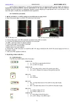
2. Mount the power supply in a RACK 19" cabinet as shown below: 


- Mount M6 cage nuts 


- Secure the enclosure with 4xM6 screws 

 
3. Connect the power cord of the recorder (included) to the DVR connector. 
4. If needed, the following technical connections can be made: 
- ALARM – technical output of collective failure 
5. Connect the battery to the +BAT- terminals: 
- battery output (V+): terminal BAT+ 
- battery output (V-): terminal BAT- 
6. Connect the ~230V AC power cord with the IEC C13 plug (included) to the 230V AC power supply and turn on 
the power (~230V). 
7. Check the PSU operation indicator. 


3.  Operating status indication. 
 

3.1.  LED indication. 
The PSU has 6 LED lights at the front panel: 


GREEN LED: 


on – the PSU is supplied with 230V AC 


off – no 230V AC supply 

 
GREEN LED: 


on – DC voltage at the output of the switch mode PSU 


off – no DC voltage at the output of the switch mode PSU 


RED LED: 


on – failure 


off – no failure 


RED LED: 


ON – too high temperature of the switch mode power supply 
(>70°C) 


OFF – standard temperature of the switch mode power supply 

 
RED LED: 


on – battery voltage <11,5V 


off – battery voltage >11,5V 

GREEN LED: 


on – DC voltage in the DVR output 


off – no DC voltage in the DVR output 


Summary of Contents for ROUPS12VR

Page 1: ...ROUPS12VR v 1 0 ROUPS 12V 5A RACK mounted buffer power supply of the recorder EN Edition 1 from 15 03 2016 Supercedes the edition ...

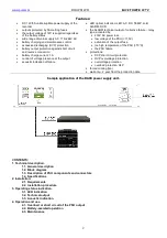
Page 2: ... failure relay type activated by 230V AC power loss low voltage of the PSU 11 5V activation of the output fuse too high temperature of the PSU 70 C the PSU failure protections SCP short circuit protection OVP overvoltage protection overvoltage protection overload protection OLP forced cooling fan warranty 2 year from the production date Sample application of the RACK power supply unit CONTENTS 1 T...

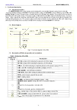
Page 3: ...osure adapted for mounting in standard RACK 19 cabinets 1 2 Block diagram Fig 1 The block diagram of the PSU 1 3 Description of PSU components and connectors Table 1 Elements of the PSU Element no Fig 2 Description AC OK green LED indicating the presence of 230V voltage DC OK green LED indicating the presence of DC voltage TEMP red LED indicating too high temperature of the power supply 70 C LoB r...

Page 4: ... 2 Mains supply 176 264V AC Current up to 0 8A 230V AC max Supply power 74W max Efficiency 71 Output voltage DVR recorder 12V DC Output current 5A recorder 1A battery charge Ripple 50 mV p p max Battery charge current 1A max 5 Short circuit protection SCP F 5A melting fuse Overload protection OLP Current consumption by PSU systems 105 150 of the PSU power automatic return 0 2A Overvoltage protecti...

Page 5: ...rst Protection grade PN EN 60529 2002 U IP20 Electrical strength of insulation between input and output circuits of the PSU I P O P between input circuit and PE protection circuit I P FG between output circuit and PE protection circuit O P FG 3000 V AC min 1500 V AC min 500 V AC min Insulation resistance between input circuit and output or protection circuit 100 MΩ 500V DC Operating parameters tab...

Page 6: ... the following technical connections can be made ALARM technical output of collective failure 5 Connect the battery to the BAT terminals battery output V terminal BAT battery output V terminal BAT 6 Connect the 230V AC power cord with the IEC C13 plug included to the 230V AC power supply and turn on the power 230V 7 Check the PSU operation indicator 3 Operating status indication 3 1 LED indication...

Page 7: ... the ON OFF position of the switch switch in the up position indication ON switch in the down position indication OFF 4 Operation and use 4 1 Overload or short circuit of the PSU output The power supply outputs are protected against short circuit by melting fuse in the case of fuse failure it should be replaced with a fuse of the same type 4 2 Battery assisted operation In case of a main power out...

Page 8: ...e are no technical possibilities to carry out the repairs or if the equipment has been conditionally accepted due to the breaking warranty terms by the claimant 7 All the services are carried out at the service centre of the manufacturer exclusively 8 The warranty does not cover the defects of the equipment resulting from reasons beyond the manufacturer s control mechanical damage improper storage...

Reviews: