www.pulsar.pl
SWS series
4
Table 2. Specifications.
Power supply
~ 200
– 240 V; 1,2 A; 50/60 Hz
Inrush current
50 A
Efficiency
85%
PoE supply
52 V DC; 150 W
Voltage adjustment range
48 V
– 53 V DC
Ripple voltage
150 mV p-p max.
Short circuit protection (SCP)
electronic, automatic recovery
Overload protection (OLP)
105
– 150% of power supply, automatic recovery
Surge protection
varistors
Over voltage protection (OVP)
> 60 V (automatic return)
Connectors
Power input:
Φ0,63-2,50 (AWG 22-10)
PoE power supply output: DC plug 2.1/5.5
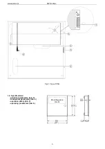
Dimensions
W=300, H=300, D+D
1
=105+8 [+/- 2mm]
W
1
=305, H
1
=305 [+/- 2mm]
W
2
=230, H
2
=110, D
2
=45 [+/- 2mm]
Enclosure
Steel sheet, DC01 1,0mm color RAL 9003
Closing
Cheese head screw x 2 (at the front, lock assembly possible)
Notes
Enclosure does not adjoin assembly surface so that cables can be led..
Additional equipment
Mounting screws (x4)
Net/gross weight
2,87 / 3,00 [kg]
Declaration
CE
Table 3. Operation safety.
Protection class EN 62368-1
I (first)
Degree of Protection EN 60529
IP20
Electrical strength of insulation:
- between input input and output circuits of the PSU
- between input circuit and protection circuit
- between output circuit and protection circuit
2500 V AC min.
1500 V AC min.
500 V AC min.
Insulation resistance:
- between input circuit and output or protection circuit
100 MΩ, 500 V DC
Table 4. Operating parameters.
Operating temperature
-
10ºC...+40ºC
Storage temperature
-
20ºC...+60ºC
Relative humidity
20%...90%, without condensation
Vibrations during operation
unacceptable
Impulse waves during operation
unacceptable
Direct insulation
unacceptable
Vibrations and impulse waves during transport
According to PN-83/T-42106
2. Installation.
2.1 Requirements.
Device is to be mounted by a qualified installer, holding relevant permits and licenses (applicable and required
for a given country) for ~230 V in and low-voltage installations. The unit should be mounted in confined spaces with
normal relative humidity (RH=90% maximum, without condensing) and temperature from -
10°C to +40°C.
As power supply is designed for a continuous operation and is not equipped with a power-switch, therefore, an
appropriate overload protection in power supply circuit should be provided. Moreover, user should be informed how to
disconnect power supply unit from mains supply (most frequently through separating and assigning an appropriate fuse in
the fuse-box).


