Specifications subject to change without notice. All dimensions in inches. © Copyright 2012 The Connor-Winfield Corporation
2111 Comprehensive Drive
Aurora, Illinois 60505
Phone: 630-851-4722
Fax: 630- 851- 5040
www.conwin.com
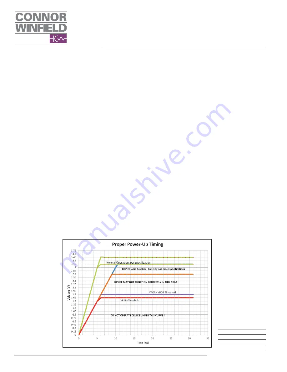
2.7 Brown-Out Reset.
When the device powers down, the device Vcc
will cross the VPOR / VBOR voltage. Once the Vcc
voltage decreases below the VPOR / VBOR voltage
the following occurs:
•
Factory serial programming interface is
disabled.
•
Non-Volatile register are no longer
programmable.
If the VCC voltage decreases below the VRAM
voltage the following occurs:
•
Volatile registers may become corrupted.
•
TCONF register may become corrupted.
•
OCXO oven core may lose thermal
equilibrium.
•
OCXO frequency stability may not meet the
data sheet specifications.
As the voltage recovers above the VPOR / VBOR
voltage see section “Power-on Reset”
On subsequent brown-out conditions where the
device is not power-cycled properly (i.e., the supply
voltages are not taken down to 0V), the power supply
voltage must be dropped below 1.6 volts in order to
clear out the EEPROM device configuration content.
2 8 Voltage Regulators.
A voltage regulator takes an input voltage from
an external source and steps it down to a suitable
voltage level that can power components on the
circuit board. Two common types of voltage regulators
are dc-dc converters and low-dropout regulators
(LDO). When deciding on a voltage regulator, always
review the regulator data sheets to match component
specifications with system requirements.
As digital logic gates of ICs switch from one
state to another, the IC’s current draw fluctuates at
a frequency determined by the logic state transition
rate or “rise-time”. These current oscillations cause
the power supply voltage to fluctuate as a small
voltage develops across the net due to its intrinsic
impedance. The circuit’s impedance can be lowered
by carefully selecting a capacitor that provides a low-
impedance path to ground for high frequencies. As a
capacitor charges or discharges current flows through
it which itself is restricted by the internal resistance
of the capacitor. This internal resistance is known as
Capacitive Reactance and is given the symbol XC
in ohms. Unlike resistance which has a fixed value,
ie 100
:
, 1k
:
, etc. Capacitive Reactance varies with
frequency so any variation in frequency will have an
effect on the capacitor. The loop from the voltage
supply pin to decoupling capacitor to ground should
be kept as small as possible by placing the capacitor
near the power supply pin and ground pin of the
device.
Application Note
AN2093
Page
3
Revision
P01
Date
10 May 2013
Summary of Contents for UM-20
Page 28: ...W J o on O O O m 5 0 u G O O O O O Omwmww 3 O f 0 016679 Lager 1 TOP ...
Page 29: ...016676 Lager 1 2121 ...
Page 31: ...016676 Bottom Soldermask ...
Page 81: ......
Page 82: ......


