background image

Seal and Spacer Replacement cont. 

Tech Support: 1-888-989-7873 

PURE WATER TREATMENT, INC. 

Page 26 

9. Alternately remove the remaining seals and 

spacers in accordance with steps No. 6 and 8. 

10. The last or end spacer odes not have any holes 

for the pins of the spacer tool to engage, 
therefore if the end spacer does not come out 
on the first try, try again using the wire hook 
with the finger loop. 

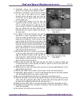
11. To replace seals, spacers and end ring, use 

special tool with the brass sleeve on one end. 
This is a double-purpose tool., (See Fig. 4). The 
male end acts as a pilot to hold the spacers as 
they are pushed into the valve body and the 
brass female end is used to insert the seals into 
the valve body. 

12. To restuff a valve body, first take the end ring 

(the plastic or brass ring without holes), then 
with your thumb press the button on the brass 
sleeve end, the large dia. inner portion is now 
exposed (See Fig. 4). Place the end ring on this 
pilot with the lip on the end ring facing the tool, 
and push the tool into the valve body bore until 
it bottoms. While the tool is in the valve body,  
take a seal and press it into the inside diameter 
of the exposed brass female end. 

13. Remove the tool, turn it end for end and insert 

it into the valve body bore. While holding the 
large dia. Of the tool, slide it all the way into the 
valve body bore until it bottoms, then push the 
center button to push the seal of the tool and 
leave it in place in the valve body. 

14. Remove the tool from the valve body and push the center on the brass female end 

to expose the pilot on the opposite end. Place a spacer on this end and insert the 
spacer and tool into the valve. 

15. While the tool is still in the valve, press another seal into the inside diameter of the 

exposed brass sleeve end. 

16. Remove the stuffer, turn it end for end, and insert it into the valve body bore. 
17. Alternately repeat steps No. 13 and 14 until all seals and spacers have been pushed 

into the valve (See valve cross section of your valve). 

18. Place recommended silicone lubricant on the piston and inside the valve. 
19. Hold the back plate with one hand and guide the piston into the valve body with the 

other hand, then grasp the back plate on both sides and slowly push the piston 
assembly and end plug assembly into the valve (See Fig. 1). 

20. Replace the two PH screws to hold the back plate to the valve and tighten securely. 
21. Connect the brine line form the injector housing to the brine valve (if your unit has 

timed brine tank fill). 

22. Set the time of day dial to the correct time. 

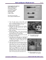
Fig. 3   Removing Spacer from       
            Valve Body 

Fig. 4   Removing Spacer from       
            Valve Body 

Summary of Contents for PTSF-2510-10

Page 1: ...For Model PTSF 2510 10 PTSF 2510 13 Owners Manual Installation Instructions...

Page 2: ...Valve Drive Assembly 18 Control Valve Drive Parts List 19 Control Valve Base Assembly 20 Control Valve Base Parts List 21 Bypass Valve Assembly Plastic 22 Bypass Valve Assembly Brass 23 Troubleshooti...

Page 3: ...Page 3 Figure A PURE TECH 2500 FLOW DIAGRAM PURE TECH 2500 TO DRAIN CLEAN WATER 2ND BALL VALVE 1ST BALL VALVE SPIGOT PURE TECH 250 PRESSURE TANK PUMP RAW WATER...

Page 4: ...Line Flow Control _____________ gpm Injector Size _______________________ TYPICAL CONTROL VALVE INFORMATION Job Specification Sheet Tank Dia Injector Inj Color Slow Rinse Rate gpm DLFC 6 0 Red 31 gpm...

Page 5: ...nd the instructions and are completely satisfied with your installation We recommend that you take a few minutes and look at the service parts manual for your particular model to help you better under...

Page 6: ...not controlled by a switch Our Fleck valves have a 5 power cord but you can use an extension cord if an outlet is not nearby Please follow any local building safety codes if you need to use an extensi...

Page 7: ...plumbing the system to 7 INSTRUCTIONS FOR USING A BYPASS If you are using our optional or 1 brass bypass valve you will need to purchase two or 1 Male thread adapters to whatever type and size pipe yo...

Page 8: ...the pipes to the system Then return it to the Bypass position before turning your water back on to the house 14 Measure and cut the lengths of pipe you need to plumb the main hard water line into your...

Page 9: ...etely over the barbed end of the fitting and then attach a small hose clamp to the end of the line so it cannot work loose over time Run the op posite end of this drain hose to the drain you are going...

Page 10: ...sound of water entering the system will stop 4 Next open one faucet preferably an outside faucet a laundry sink or bathtub let ting the water run through it slowly for a few minutes This allows the w...

Page 11: ...4 You are now ready to experience PURE WATER Don t forget to tell your friends family and neighbors about how excellent the PURE TECH 2500 works for you Post Installation Even though you now have PURE...

Page 12: ...ball valve back to the open position 7 You will need to add chlorine to the system once every 2 to 3 months 8 The system will manually backwash itself clean If you find that the system is not produci...

Page 13: ...Feeder and close spigot 5 Add Chlorine Pellets to Pot Feeder DO NOT MIX DIFFERENT TYPES OF CHLORINE OR EXPLOSION WILL OCCUR SEE PAGE 29 FOR LIST OF CHLORINE MANUFACTURERS 6 Close Pot Feeder turn ball...

Page 14: ...revolution in the following approximately three hours and stop in the po sition shown in the drawing Even thought it takes three hours for this center knob to complete one revolution the regeneration...

Page 15: ...h Time The program wheel as shown in the drawing is in the service position As you look at the numbered side of the program wheel the group of pins starting a zero determines the length of time your u...

Page 16: ...Timer Assembly Tech Support 1 888 989 7873 PURE WATER TREATMENT INC Page 16...

Page 17: ...5424 Spring Main Gear Detent 13 1 13911 Main Drive Gear 14 1 19210 Program Wheel 15 21 15493 Roll Pin 16 1 13018 Idler Shaft 17 1 13312 Spring Idler 18 1 13017 Idler Gear 19 1 13164 Drive Gear 20 1 13...

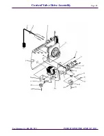
Page 18: ...Control Valve Drive Assembly Tech Support 1 888 989 7873 PURE WATER TREATMENT INC Page 18...

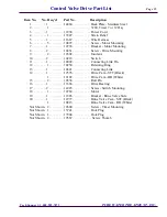
Page 19: ...231 Screw Drive Mounting 9 2 10302 Insulator 10 2 10218 Switch 11 1 10909 Connecting Link Pin 12 1 10250 Retaining Ring 13 1 10621 Connecting Link 14 1 12576 Drive Cam STF Black 1 12102 Drive Cam RR W...

Page 20: ...Control Valve Base Assembly Tech Support 1 888 989 7873 PURE WATER TREATMENT INC Page 20...

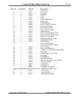
Page 21: ...Nozzle Specify Size 16 1 10229 Injector Cover Gasket 17 1 11893 Injector Cap Plastic Body 18 2 10692 Injector Body Screw 19 1 18312 Drain Retainer 20 1 Flow Control Washer Specify Flow Rate in GPM 21...

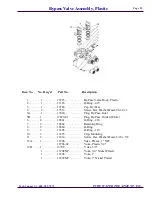
Page 22: ...1 17820 Plug By Pass Inlet 5B 1 17820 01 Plug By Pass Outlet White 6 4 18661 O Ring 218 7 2 18662 Retaining Ring 8 2 18660 O Ring 9 2 13305 O Ring 119 10 2 13255 Clip Mounting 11 2 13314 Screw Hex Wa...

Page 23: ...ve Body 3 4 1 17290NP By Pass Valve Body 3 4 Nickel Plate 1 13399 By Pass Valve Body 1 1 13399NP By Pass Valve Body 1 Nickel Plate 2 1 11726 Seal By Pass 3 1 11972 Plug By Pass 4 1 11978 Side Cover 5...

Page 24: ...dd Mineral Cleaner to Mineral Bed Increase Frequency of Regeneration C Inlet of Control Plugged Due to foreign material broken loose from pipes by recent work done on plumbing system C Remove Piston a...

Page 25: ...ble pins retained by a rubber ring at one end they are retracted or pushed out by pulling or pushing the center button the opposite end 8 Insert the pin end of the spacer tool into the valve body with...

Page 26: ...d insert it into the valve body bore While holding the large dia Of the tool slide it all the way into the valve body bore until it bottoms then push the center button to push the seal of the tool and...

Page 27: ...ech Support 1 888 989 7873 PURE WATER TREATMENT INC Figure A 1 5 3 2 1 Flow rate control 2 Large 1 1 2 in and out flow 3 Drain to release pressure or clean unit 4 Clearly labeled flow direction 5 Easy...

Page 28: ...htly Securely tighten but be careful not to strip the threads Install required plumbing bushings in PURE TECH 250 that matches your pipe size Install PURE TECH 250 after ball valve With this installed...

Page 29: ...7873 PURE WATER TREATMENT INC Please contact one of these companies to find a dealer near you Company Phone Number Product OSMONICS 1 800 848 1750 Well Pro Pellets Krudico 1 800 211 1369 Pell Chlor Be...

Page 30: ...ally this warranty does not cover products installed for commercial industrial institutional or multi family applications The design of the overall treatment system and performance of your system is r...

Page 31: ...____________________________________________________________ ________________________________________________________________________ __________________________________________________________________...

Reviews: