Edition from 03.06.2015
7
PLC330.
Multichannel stepper motor driver
www.purelogic.ru
8 (800) 555 63 74
05. Connection
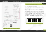
Fig. 2.
Connection and setup of PLC330
05
Connection
Control signals connection
Multichannel driver PLC330 controls 4 stepper motors using standard
signals STEP/DIR/ENABLE.
The driver of every channel has its couple of signals STEP1/2/3/4 and
DIR1/2/3/4 and signal ENABLE is mutual for all the channels. н
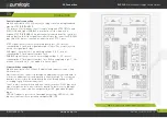
Signals STEP/DIR/ENABLE are galvanically isolated from the controller
and are buffered. All the signals are allocated to the connector DB-25M
type (fig.2) for a more convenient connection to LPT PC port.
STEP signal characteristics are working voltage 3...5V, current
consumption 0.1 mА, min signal duration is 10ms. The step is carried
out on the signal back edge.
DIR signal characteristics are working voltage 3...5V, current
consumption 0.1 mА, operation time 1 ms.
ENABLE signal characteristics are working voltage 3...5V, current
consumption 0.1 mА, operation time 1 ms. When supplying logic ‘1’, the
module is turned on, ‘0’, the module is switched off.
Limit switches connection
Multichannel driver PLC330 has 5 optoisolated inputs for connecting
limit switches.
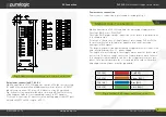
Limit switches are connected through an additional extension board. A
scheme of additional extension board is shown in fig.3. The extension
board is connected to the main board via a tail through adapter XP5
according to gig.2 (Alarm connector).
Usual contact limit switched and non-contact sensors PLL01 type with
signal output can be connected to the board. To do this every group of
limit switches connection has output v5V, ground and signal
input.
LED HL1 indicates presence of board power voltage, LEDs HL2...HL6
indicate limit switches operation on inputs IN5...IN1.


