Edition from 03.06.2015
9
PLC330.
Multichannel stepper motor driver
www.purelogic.ru
8 (800) 555 63 74
05. Connection
Relay loads connection К1, К2, К3
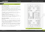
Multichannel driver PLC330 supports control of 2 high current relays
К1 and К2 for commutation of additional machine devices. LED HL1
indicates operation of K1 relay, HL2 indicates relay K2 operation.
Fig. 2 shows relay commutation when switched off. Control of every
relay happens from the corresponding contact in XP1 adapter.
Please note that relay K1 operates in controlling mode from LPT port
only when JMP1 switch is open in XP13.
Power source connection
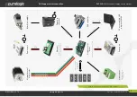
Power source connection is performed according to fig. 6.
Multichannel driver PLС330 is optimal for operating stepper motor
Purelogic R&D series PL42/PL57.
Purelogic R&D stepper motor connection to the driver is performed as
it is shown in fig. 6.
Please note that in case of couple (phase) interchange PH1.x<>PH2.x,
the motor will start rotating in the opposite direction (inversion
analogue of DIR signal).
The driver has protection against wrong stepper motor coil connection
and coils linked together / ‘+’ power supply.
The length of wires leading to the stepper motor from the driver must
not exceed 10 meters. Longer wires can lead to driver’s work failures.
It is strongly recommended to interlace the stepper motor wires per
phase, then put this braid to the screened metal sheathes. Sheathes
and stepper motor frame must be grounded.
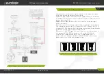
Fig. 3.
Additional extension board, limit switches connection
Stepper motor connection
06
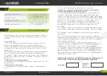
Fig. 4.
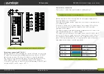
Purelogic R&D stepper motor connection
PH1.1 [+А]
Red (RED)
PH1.2 [-А]
Orange (ORG)
PH2.1 [+B]
Blue (BLU)
PH2.2 [-B]
Green (GRN)


