background image

13 

Copyright © Puretec Pty Ltd 2016

Puretec MUL -E1 User Guide

Installation

Programming 


6.1 Plug into an uninterrupted electrical outlet.


Note: All electrical connections must be connected accordingly to local codes.

6.2 Proceed to ‘Programming’ section

11

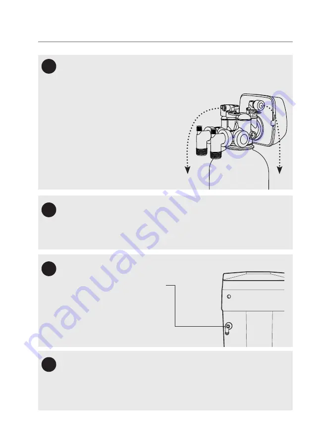
Connecting the drain line. 

Locate the 300mm drain tube and attach to the drain 

connection, refer to page 9 for identification of the drain port.

Connecting the overflow

Connecting brine line

8

10

9

Connect tubing onto the 5/8” overflow 
fitting (tubing not supplied) and run the 

line to the drain. 

Do not connect the 

overflow into the drain line

, as it must 

be a direct and separate line to the 
drain. Allow an air gap as per the drain 
line. Make sure the drain is not higher 

than the overflow.

Locate Elbow Fitting in the Brine Tank, remove black tubing and dispose. Connect 2m 
length of 3/8 black tubing between Brine Line and Elbow Fitting. 
(refer to diagrams in step 8 and 10)

Connect extra tube (tubing not supplied) 

onto the 5/8” drain line from the valve 

to the drain. Ensure the drain line is not 
kinked. The line must not travel more 
than 2.4m up from the valve, otherwise 
increase the diameter of the drain line.

Connect drain and overflow to sewer or 

stormwater, whatever is approved by local 
authority for salty discharge water.

Ensure drain line has an adequate air gap 
of 2 times the pipe diameter or 25mm, 
whichever is larger.

OVERFLOW

BRINE

BRINE

DRAIN

Summary of Contents for MUL-E1 Series

Page 1: ...User Guide Multitrol Filtration System MUL E1 Series For correct operation installation it is essential to observe these instructions MAR2018 ...

Page 2: ... Before Installation 5 Specifications 7 Exploded Diagram 8 Diagram Identification 9 Installation Procedure 10 Programming 14 Start up 15 Regeneration 15 Replenishment of Salt Supply 16 Type of Salt to Use 16 Brine Tank Clean Out Yearly 16 Media Replacement 16 Bypass Valve Operation optional accessory 17 Troubleshooting Guide 18 Warranty 22 ...

Page 3: ...ation is applicable to your particular unit Caution Do not use with water that is microbiologically unsafe or without adequate disinfection before or after the system Puretec systems are designed to run economically for many years and this is dependant on the initial installation and periodic maintenance Flush system for 5 minutes or more after any period of non use more than 2 weeks Note For poin...

Page 4: ...er Plumber Details Regen Frequency ________ Days Water Analysis Information Hardness ___________ ppm mg L Iron ___________ ppm mg L Manganese ___________ ppm mg L pH ___________ TDS Total Dissolved Salts ___________ ppm mg L Ammonia ___________ ppm TOC Tannin ___________ ppm Installation Record For future reference fill in the following data Pre installation ...

Page 5: ...and hardness Contact Puretec when selecting model and regeneration settings for best results Install Water Conditioning Equipment Correctly Select the location of your Multitrol system with care Various conditions which contribute to proper location are as follows Install as close as possible to a drain Install in correct relationship to other water treatment equipment Contact Puretec for assistan...

Page 6: ...etting primer and solvent cement on filter system Install grounding strap on metal pipes if required Ensure the system is protected against high pressure and extreme temperatures Facts to Remember While Planning Your Installation All installation procedures MUST conform to local plumbing codes If lawn sprinkling a swimming pool or geothermal heating cooling or water for other devices activities ar...

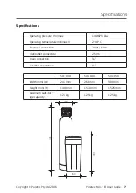
Page 7: ...in max 140 875 kPa Operating temperature min max 2 48 C Electrical connection 240V 50 Hz Inlet outlet connection 25mm Drain connection Overflow connection SOL C30 SOL C40 SOL C50 Width mm W 245 mm 260 mm 300 mm Height mm H 1400 mm 1570 mm 1525 mm Maximum salt stor age capacity 125 kg 125 kg 125 kg W 430 900 H ...

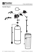
Page 8: ...8 Installation Operation Manual Copyright Puretec Pty Ltd 2018 Parts Identification Exploded Diagram 2 1 3 4 5 7 6 10 9 11 12 13 14 15 8 ...

Page 9: ... Top screen 4 WTD3030 Pressure tank UV sheild 5 WTV4000 Automatic valve 6 WTB5070 Plastic fitting kit elbow 7 WTB2100 Valve Cover 8 Drain tube assembly 9 WTV5135 Transformer suit auto valve Item Part no Description 10 WTV5000 Bypass assembly purchased Separately 11 KTV6SVC Black tubing 12 KEC66 Elbow connector 13 WTB4190 Brine pickup assembly 14 WTB2200 Brine tank 15 WTB5150 2 Peice overflow Brine...

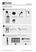
Page 10: ...____ ppm mg L pH ___________ TDS Total Dissolved Salts ___________ ppm mg L Conductivity ___________ EC uS cm Chloride ___________ ppm mg L Sodium ___________ ppm mg L 130 0 3 0 1 7 275 404 121 96 Customer Service Helpline 1300 140 140 AU 0800 130 140 NZ Extra items required 2 Unpack the equipment Locate and identify the parts as shown below 1 User Guide Multitrol Filtration System MUL E1 Series F...

Page 11: ...far enough away from any water heaters to avoid any hot water backflow into the system A weatherproof powerpoint and surge protector is recommended 2 Plug or cover the top end of the riser pipe in the tank making sure no media can enter the tube 3 Ensure that the riser pipe is sitting in the cradle at the base of the tank Then using a wide mouth funnel place the media in the tank as per the number...

Page 12: ... control module 7 Apply plumbing tape to the nipple as required Connect the pipe work to the valve refer to page 9 for identification FOLLOW LOCAL PLUMBING CODES Installing the Bypass purchased separately Uninstall the plastic fittings by turning the knob coun terclockwise Connect the bypass assembly followed by the plastic fittings Hand tighten the knobs do not overtighten Refer to page 17 for by...

Page 13: ...ust be a direct and separate line to the drain Allow an air gap as per the drain line Make sure the drain is not higher than the overflow Locate Elbow Fitting in the Brine Tank remove black tubing and dispose Connect 2m length of 3 8 black tubing between Brine Line and Elbow Fitting refer to diagrams in step 8 and 10 Connect extra tube tubing not supplied onto the 5 8 drain line from the valve to ...

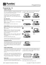
Page 14: ...M If there is a demand for water when the system is regenerating untreated water will be used SET TIME OF DAY Step 1 Press SET for 5 seconds Step 2 Current time set HOUR by using the button then press SET Repeat for MINUTES After a power outage the time of day will need to be reset Programming E1 Time Hour PM Days To Regen Regen Min Fill Regen Hour SET SET Time Hour PM Days To Regen Regen Min Fill...

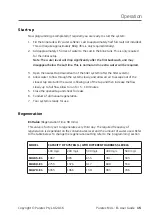
Page 15: ...llow water to flow through the system slowly and allow all air to escape out of the closest tap Wait until the water is flowing out of the tap and then increase the flow slowly up to full flow Allow to run for 5 10 minutes 5 Close the opened tap and check for leaks 6 Conduct a full manual regeneration 7 Your system is ready for use E1 Valve Regeneration Time 90 mins This valve is factory set to re...

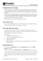
Page 16: ... using coarse solar salt called water softener salt or alternatively pool salt Brine Tank Clean Out Yearly To help prevent service problems the brine tank should be emptied and flushed out with a garden hose when dirt and other insolubles accumulate on a regular basis Shut off water inlet supply and depressurize the system before service Steps to follow 1 Disconnect brine line at either end 2 Turn...

Page 17: ...PLY WATER ENTERS NO WATER EXITS SUPPLY WATER IS SHUT OFF FROM THE HOUSE THE VALVE TREATED WATER EXITS SUPPLY WATER ENTERS SUPPLY WATER EXITS SUPPLY WATER ENTERS Normal Operation Bypass Operation Diagnostic Mode Shut Off Mode Bypass Valve Operation optional accessory Bypass operation ...

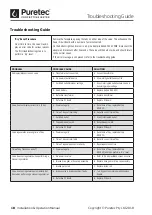
Page 18: ...ion set incorrectly C Reset regeneration time Time of day flashes on and off A Power outage s A Reset time of day replace battery CR2032 and then perform a dry reset Valve does not regenerate when performing a manual regeneration A No power to valve A Refer to No display blank screen on valve B Broken drive gear or drive cap assembly B Replace drive gear or drive cap assembly C Broken piston rod C...

Page 19: ...correct refill setting A Contact Puretec for assistance B Incorrect program setting B Contact Puretec for assistance C Valve regenerating frequently C Check for leaking fixtures or system under sized Regenerant being delivered to service A Low water pressure A Check incoming water pressure water pressure must remain at minimum of 25 psi B Incorrect injector size B Replace injector with correct siz...

Page 20: ...eplace drive cap assembly Error Code 1001 Control unable to sense motor movement A Motor not inserted fully into engage posi tion motor wires broken or disconnected A Disconnect power make sure the motor is fully engaged check for broken wires make sure two pin connector is connected to the two pin connection on the PC Board labelled MOTOR Connect power and per form a dry reset B PC Board not corr...

Page 21: ...or connections Perform a dry reset B Foreign material lodged in valve B Clean replace piston spacer stack assembly Perform a dry reset C Drive bracket not correctly installed C Snap drive bracket in correctly Perform a dry reset Error Code 1004 Control valve motor ran too long and timed out trying to reach home position A Drive bracket not correctly installed A Snap drive bracket in correctly Perf...

Page 22: ...be pursued at Puretec s discretion including chargeable inspection and labour costs incurred Warranty Australia This warranty is given by Puretec Pty Ltd ABN 44 164 806 688 37 43 Brodie Road Lonsdale SA 5160 telephone no 1300 140 140 and email at sales puretec com au This warranty is provided in addition to other rights and remedies you have under law Our goods come with guarantees which cannot be...

Page 23: ......

Page 24: ......

Reviews: