10
Reverse Osmosis Water Treatment System
Copyright © Puretec Pty Ltd 2020
Step 4: Make Tubing Connections
The connections to the faucet should be complete, the remaining connections are:
•
Feed connection—clear tubing from feed valve to white elbow connector
•
Drain connection—either red tubing from the air gap or black tubing from grey elbow
connector will attach to the drain adapter
•
Permeate connection—blue tubing from faucet to blue elbow connection
•
Attach the fittings to the manifold
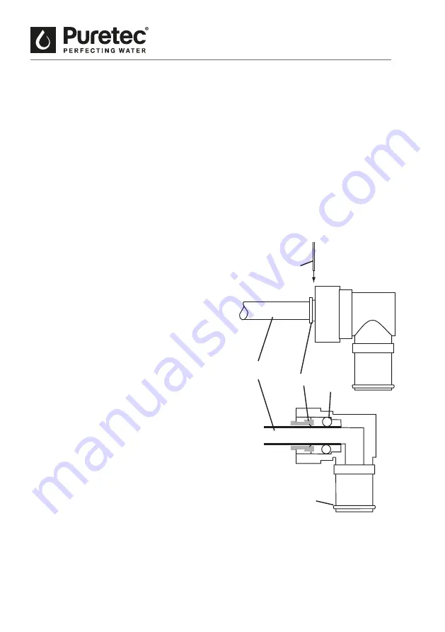
A typical connection is shown in Figure 6 Side View and Cutaway of Tubing Fitting.
Note
: For optimal system performance, we recommend using tubing lengths that are as short
as possible.
Post filter
Install the post filter in line with the blue permeate
tubing. Make sure flow direction aligns with water
path. Secure tubing with collet lock clips.
Drain Adapter (Optional)
The drain adapter has a rubber inlet that accepts
the 3/8 inch black drain tube or the 1/2 inch red
tube. The 3/8 inch black tubing will connect here if
the faucet is not using the air gap module.
When the tubing is in position, use the supplied
hose clamps to secure the connection.
Note
: When sliding tubing into the drain adapter
inlet, wet the tubing. Water will help the tubing
slide into the rubber inlet.
Feed Pressure Gauge
The supplied pressure gauge can be connected
to the feed line to monitor system feed pressure.
For proper system performance, the dynamic feed
pressure must be between 275 kPa and 520 kPa
when the system is in operation.
Caution
: The feed pressure gauge is intended for
use only durin installation and troubleshooting
of the RO system. The pressure gauge should be
removed during normal system operation because
some regulatory agencies did not evaluate the RO
system with the feed pressure gauge in place.
Note
: Make sure the tubing is pushed past
the O-rings for a secure fit. Also, when
replacing any tubing, cut tubing back 1/4
inch prior to re-inserting to prevent leaks.
Side View and Cutaway
of Tubing Fitting
Installation Guide
NOTE: Make sure the tubing is pushed past the O-rings for a
secure fit. Also, when replacing any tubing, cut tubing
back ~1/4 inch prior to re-inserting to prevent leaks.
INSTALLATION cont.
Step 4: Make Tubing Connections
The connections to the faucet should be complete, the remaining
Feed connection—clear tubing from feed valve to white elbow
Drain connection—either red tubing from the air gap or black
tubing from grey elbow connector will attach to the drain
Permeate connection—blue tubing from faucet to blue elbow
Attach the fittings to the manifold
A typical connection is shown in Figure 7 Side View and Cutaway of
NOTE: For optimal system performance, we recommend using tubing
lengths that are as short as possible.
Install the postfilter in line with the blue permeate tubing. Make sure
flow direction aligns with water path. Secure tubing with collet lock
Drain Adapter (Optional)
The drain adapter has a rubber inlet that accepts the 3/8-inch black
drain tube or the 1/2-inch red tube. The 3/8-inch black tubing will
connect here if the faucet is not using the air gap module.
When the tubing is in position, use the supplied hose clamps to
secure the connection.
NOTE: When sliding tubing into the drain adapter inlet, wet the
tubing. Water will help the tubing slide into the rubber inlet.
Feed Pressure Gauge
The supplied pressure gauge can be connected to the feed line to
monitor system feed pressure. For proper system performance, the
dynamic feed pressure must be between 40 psi (2.76 bar) and 80 psi
(5.52 bar) when the system is in operation.
The feed pressure gauge is intended for use only during
O-Ring
O-Ring
Collet
Tubing
Collet
Lock Clip
Figure 7 Side View and Cutaway of Tubing Fitting
Fig. 6


