background image

User Manual


PT-SP-HD14BT 


11 


3.


System Connection 

3.1


Usage Precautions 


Verify all components and accessories included before installation. 


System should be installed in a clean environment with proper temperature and 

humidity (see page 22 for limits). 


All of the power switches, plugs, sockets and power cords should be insulated 

and safe. 


All devices should be connected before power on. 


Summary of Contents for PT-SP-HD14BT

Page 1: ...User Manual PT SP HD14BT User Manual 1x4 Splitter 4K HDMI over HDBaseT Model PT SP HD14BT Designed in Germany 2017 PureLink GmbH All rights reserved VersionV1 0 ...

Page 2: ...pied or reproduced without the prior written consent FCC Statement This equipment generates uses and can radiate radio frequency energy and if not installed and used in accordance with the instructions may cause harmful interference to radio communications It has been tested and found to comply with the limits for a Class B digital device pursuant to part 15 of the FCC Rules These limits are desig...

Page 3: ...1907 2006 EU und 2011 65 EU EMC LVD Electro Magnetic Compatibility Low Voltage Directive PureLink GmbH hereby declares that this product PureTools PT SP HD14BT complies with Directives 2014 30 EU and 2014 35 EU The full text of the EU Declaration of Conformity is available at the following Internet address http www purelink de ce 4251364709030_CE pdf ...

Page 4: ...r install this product near water Do not put any heavy items on the extension cable in case of extrusion Do not remove the housing of the device as opening or removing housing may expose you to dangerous voltage or other hazards Install the device in a place with fine ventilation to avoid damage caused by overheat Keep the module away from liquids Spillage into the housing may result in fire elect...

Page 5: ...sage Precautions 11 3 2 System Diagram 12 3 3 Cascading 13 4 IR Control 14 4 1 Controlling the Display Device by IR IN 14 4 2 Controlling the Display Device by IR ALL IN 15 4 3 Controlling the Source Device 16 5 RS232 Control 17 5 1 RS232 Control Software 17 5 2 RS232 Command Format 19 6 EDID Management 21 7 Technical Specification 22 8 Panel Drawing 24 9 Troubleshooting Maintenance 25 10 After Sa...

Page 6: ...rd Ethernet cables It supports bidirectional IR and RS232 pass through and loop output 1 1 Features Splits a single HDMI input to four HDBaseT outputs and one HDMI loop output Supports video resolutions up to 4K 60Hz 4 2 0 Extends 1080p signals on each output to distance up to 70 meters and 4K signals to distance up to 40 meters over a CATx Ethernet cable Supports Power over HDBaseT PoH allowing c...

Page 7: ...ircular Plastic Cushions 1x 3 pin to 3 pin RS232 Cable for RS232 loop out cascading 1x 3 5mm Audio Cable for IR loop out cascading 4x IR Receivers 1x IR Emitter 1x Power Adaptor 24V DC 2 71A 1x User Manual Note Please contact your distributor immediately if any damage or defect in the components is found ...

Page 8: ...uminates green when there is a valid connection between the splitter and each of the four receivers HDCP Each HDCP LED illuminates green when the corresponding receiver supports HDCP and blinks green when the corresponding receiver does not support HDCP Each LED is off when there is no connected corresponding receiver EDID DIP switch for the Extended Display Identification Data EDID value setting ...

Page 9: ...port for connecting four HDBaseT receivers IR IN Four 3 5mm IR input jacks for connecting the four IR receivers IR Control IR ALL IN LOOP IN 3 5mm IR IN jack for connecting an IR receiver or cascading to previous device IR OUT 3 5mm IR OUT jack for connecting an IR emitter IR LOOP OUT A 3 5mm IR LOOP output jack for cascading to next device ID PRESET DC 24V OUTPUTS RS232 OUT Tx Rx RS232 IN Tx Rx H...

Page 10: ... in the chain ID PRESET Assigns a single digit ID to the splitter when cascading multiple splitters and using RS232 control each splitter must have a unique ID Use a small flathead screwdriver to set the ID There are sixteen positions with 0 at the fully counterclockwise position and F at the fully clockwise position After setting the ID the device must be restarted for the new ID to take effect D...

Page 11: ...ts and accessories included before installation System should be installed in a clean environment with proper temperature and humidity see page 22 for limits All of the power switches plugs sockets and power cords should be insulated and safe All devices should be connected before power on ...

Page 12: ...ivers have no need of power adaptors they can be powered by the splitter with PoH support RX TX ID PRESET DC 24V OUTPUTS RS232 OUT Tx Rx RS232 IN Tx Rx HDMI INPUT HDMI IR OUT CONTROL IR IN IR IN IR IN IR IN HDBT 1 HDBT 2 HDBT 3 HDBT 4 Laptop IR Emitter IR Receiver DVD Remote IR Emitter IR Receiver Display Remote 1080P 70M 4K 40M DVD 4K TV Receiver Display HDMI IR HDBT RS232 ...

Page 13: ...ing The splitter supports cascade connection to distribute video signal to multiple video displays Use the following connection diagram as a guide for cascading multiple units Note that each unit must have a unique ID if using RS232 control ...

Page 14: ...ce by IR IN The four IR IN ports of the splitter can receive IR signals from remotes to send to control displays Connect four IR receiver to IR IN ports of the splitter and then connect four IR emitters to IR OUT ports on HDBaseT receivers RX TX RX TX ID PRESET DC 24V OUTPUTS RS232 OUT Tx Rx RS232 IN Tx Rx HDMI INPUT HDMI IR OUT CONTROL IR IN IR IN IR IN IR IN HDBT 1 HDBT 2 HDBT 3 HDBT 4 4K TV 4 I...

Page 15: ...ceiver to IR ALL IN port of the splitter and then connect four IR emitters to IR OUT port on HDBaseT receivers RX TX RX TX ID PRESET DC 24V OUTPUTS RS232 OUT Tx Rx RS232 IN Tx Rx HDMI INPUT HDMI IR OUT CONTROL IR IN IR IN IR IN IR IN HDBT 1 HDBT 2 HDBT 3 HDBT 4 4K TV 4 IR Emitter Receiver 4K TV 1 IR Emitter Receiver IR Receiver T 1 2 3 4 Remote 1080P 70M 4K 40M 1080P 70M 4K 40M DVD HDMI IR HDBT ...

Page 16: ...orts on HDBaseT receivers and then connect an IR emitter to IR OUT port of the splitter RX TX RX TX ID PRESET DC 24V OUTPUTS RS232 OUT Tx Rx RS232 IN Tx Rx HDMI INPUT HDMI IR OUT CONTROL IR IN IR IN IR IN IR IN HDBT 1 HDBT 2 HDBT 3 HDBT 4 4K TV 4 Receiver 4K TV 1 Receiver IR Receiver DVD Remote IR Receiver DVD Remote 1080P 70M 4K 40M 1080P 70M 4K 40M DVD IR Emitter HDMI IR HDBT ...

Page 17: ...The Splitter Extender requires the following communication protocol parameters 5 1 RS232 Control Software Installation Copy the control software file to the computer connected with the splitter Uninstallation Delete all the control software files in corresponding file path Basic Settings First to connect all input devices and output devices needed then to connect it with a computer which is instal...

Page 18: ...e 8 data bits 1 stop bit no parity bits Please set the parameters of COM number bound rate data bit stop bit and the parity bit correctly and then commands are ready to send in Command Sending Area Parameter configuration area Monitoring area indicates if the command sent works Command sending area ...

Page 19: ...to PC and the others are connected to the third party devices these third party devices can be controlled by following these steps 1 First according to the below format to send the command to select the unit to receive commands Fixed value The unit ID of splitter x 0 9 A F Fixed value 2 Second send the specific control command data HEX to control the select third party devices For specific command...

Page 20: ... on off HDBaseT outputs Take the unit ID of 2 for example 1 First send F5 BB 6F 20 to select the unit to receive commands 2 Second according to the below format to send the command to switch on off HDBaseT outputs Fixed value The four X represent four HDBaseT outputs X 0 OFF X 1 ON If the HDBT 1 port need to be turned on other ports are closed the command AB AC BC 10 00 should be sent AB AC BC XX ...

Page 21: ...be used to set the EDID to a fixed value Switch Status Description L RES The splitter reads EDID from all connected displays and then the source device will automatically obtain the EDID which contain the lowest resolution DEFAULT Reset to the default EDID to distribute 4K 30Hz video H RES The splitter reads EDID from all connected displays and then the source device will automatically obtain the ...

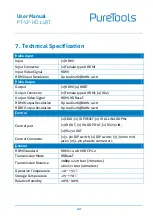
Page 22: ...utput Resolution Up to 4Kx2K 60Hz 4 2 0 HDBT Output Resolution Up to 4Kx2K 60Hz 4 2 0 Control Control port 1 EDID 1 ID PRESET 1 IR ALL IN LOOP IN 1 IR OUT 1 IR LOOP OUT 1 RS232 IN 1 RS232 OUT Control Connector 1 3 pin DIP switch 1 DIP switch 3 3 5mm mini jacks 2 3 pin phoenix connectors General HDMI Standard HDMI 1 4 with HDCP 2 2 Transmission Mode HDBaseT Transmission Distance 1080p 229 feet 70 m...

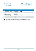
Page 23: ... Input Power 100V 240V AC 50 60Hz Input Power 24V DC 2 71A Power Consumption 45W Max Dimension W H D 220mm x 44mm x 148mm Net Weight 725g Note Please adopt quality CAT Ethernet cable compliant with CAT6e or higher standard for reliable transmission ...

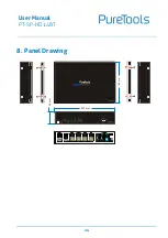
Page 24: ...User Manual PT SP HD14BT 24 8 Panel Drawing 220 mm 44 mm 148 mm ...

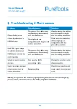
Page 25: ...resolution No HDMI signal output in splitter while local HDMI input is in normal working state The connecting cables may not be connected correctly or it may be broken Check whether the cables are connected correctly and in working condition Splash screen in output devices Poor quality of the connecting cable Change for another cable of good quality Static becomes stronger when connecting the vide...

Page 26: ...a fee Warranty expiration Factory applied serial number has been altered or removed from the product Damage deterioration or malfunction caused by Normal wear and tear Use of supplies or parts not meeting our specifications No certificate or invoice as the proof of warranty The product model showed on the warranty card does not match with the model of the product for repairing or had been altered ...

Page 27: ...User Manual PT SP HD14BT ...

Page 28: ...e Technical Support Phone 49 5971 800299 0 Fax 49 5971 800299 99 Technical Support Hours 8 30 AM to 5 00 PM Monday thru Thursday 8 30 AM to 4 00 PM Friday Write to PureLink GmbH Von Liebig Straße 10 D 48432 Rheine www purelink de info purelink de ...

Reviews: