background image

EN

40


Operating Manual: PX-iP - Gateway

Remedy:


f

Restore power supply


f

Replace rechargeable battery if 

necessary (see FAQ)

Connection fault – IP network


4

Gateway button (B) flashes at 

regular intervals

(B)


Internet outage


Router defective or without  

grid power

Remedy:

(1) 

With other devices, check whether 

an Internet connection exists


f

Inform Internet provider if necessary

(2) 

Check Internet connection of the 

router

(3) 

Restore power supply

(4) 

Restart router

(5) 

Replace router if necessary (see FAQ)

WI-FI connection to the 

router is faulty


WI-FI error, e.g., after a power outage  

or due to changed WI-FI settings

Remedy:

(1) 

Check configuration of the router

(2) 

Set up gateway connection again 

(see chapter 4.6 “Gateway setup“ 

on page 18)

LAN connection to the 

router is faulty


4

Gateway button (B) flashes at 

regular intervals

(B)


LAN cable not plugged in 

correctly or defective

Remedy:

(1) 

Check plug connection of the LAN 

cable

(2) 

Check LAN cable and replace if 

necessary

Summary of Contents for PX-iP

Page 1: ...PX iP Gateway Operating Manual ...

Page 2: ... Content 1 Notes on the operating manual 3 2 Safety instructions 9 3 Overview 14 4 Commissioning and setting up 16 5 Reset 24 6 Installation variants 26 7 Messages 29 8 Troubleshooting 33 9 Maintenance 44 10 Decommissioning 45 11 Accessories spare parts and service 46 12 Glossary 46 13 Technical specifications 47 14 Alarm and alert tones 49 ...

Page 3: ... PX iP gateway is hereinafter referred to as gateway or device and the smoke alarm device with radio link is referred to as smoke alarm device 1 1 Scope of operating manual The operating manual only applies for the gateway 1 2 Applicable documents The gateway is used in combination with the manufacturer s smoke alarm devices with radio link e g PX 1C In addition to this operating manual also obser...

Page 4: ...following directives LowVoltage Directive 2014 35 EU EMC Directive 2014 30 EU R TTE Directive 2014 53 EU Environmentally compatible design for energy related products 2009 125 EC Waste Electrical and Electronic Equip ment Directive disposal 2012 19 EU Restriction on the use of certain haz ardous substances in electrical and electronic equipment 2011 65 EU in accordance with EN 301 489 1V1 9 2 EN 5...

Page 5: ...ings and symbols are used in the text in the operating manual These are explained below Warning symbol in warning labels Additional information and guidelines 1 Numbered action steps f f Symbol for an instruction or a required action 5 5 Result of an action 4 4 Problem associated with an action Symbol for a list Light signal of the signal LED Length of the signal tone or interval Volume of a signa...

Page 6: ...GmbH This also applies for online auctions but is not limited thereto Rights arising from stat utory regulations remain unaffected by the limited warranty f f Please keep your receipt as proof that the device has been purchased from PyrexxTechnologies GmbH or from an authorized dealer and as a proof of purchase date This receipt is mandatory for any warranty claims The limited warranty will be gra...

Page 7: ...or continuously to a temperature below 0 C or above 70 C any warranty claim shall be forfeited Excessive rechargeable battery load The device s rechargeable battery is used for emergency power supply e g during a power failure and it can be recharged a limited number of times Excessive device operation via this rechargeable battery and premature consumption of the limit ed number of charge cycles ...

Page 8: ...e limited to the duration of this warranty 1 11 Limitation of liability Your rights are limited to the repair or replacement of this device as shipped Pyrexx Technologies GmbH shall accept no liability for any special incidental or consequential damages including but not limited to resulting loss of revenue loss of profits restrictions of the use of software hardware loss or recovery of data cost ...

Page 9: ...wing purposes Communication with smoke alarm devices from another manufacturer Fire alarm system as specified in EN 54 and DIN 14675 2 1 Representation and display of warning labels The warning labels are action oriented they are structured and graded as follows CAUTION Type and source of the risk Explanation about the type and source f f Measures to prevent the risk CAUTION Potential minor injuri...

Page 10: ...ll measures to ensure safety thematically and applies at all times General information Neither the gateway nor the smoke alarm devices connected to it directly transmit an alarm to an official entity that can pro vide help fire brigade The gateway is subject to strict quality controls during production In addition a function test is performed before delivery Nevertheless unexpected malfunctions ca...

Page 11: ...phone the gateway or the smoke alarm device On request Pyrexx customer support will delete your data from its IT system Replacing the rechargeable battery Under some circumstances you must re place the rechargeable battery e g if the provided rechargeable battery is defective or if the charge cycles have been used up CAUTION Danger of explosion if the re chargeable battery is not replaced properly...

Page 12: ...on Grease Nicotine and paint fumes Paint finishes e g wall paint Adhesives Contamination of any kind Immersion in water Immersion in water can damage the device f f Do not immerse the device in water Opening the device The device is a closed system Any tam pering with the device in addition to the loss of the limited warranty and statutory warranties also means that the device cannot and must not ...

Page 13: ...perating Manual PX iP Gateway EN 13 Sensitive components The device consists of sensitive components f f Do not throw the device f f Do not let the device fall f f Do not exert any pressure on the device ...

Page 14: ...ces to the user via SMS or email Read out and analysis of measured data of the connected smoke alarm devices Notification In the event of a fire alarm the gateway can relay a notification via SMS or email In the web app you can specify who receives the alarm see chapter 4 11 Notification on page 22 The gateway itself does not generate any alarm signal 3 2 Controls The gateway is controlled via but...

Page 15: ...used as to protect the gate way from failure during an interruption of the power supply e g power outage In this case the energy supply is assured over a period of at least 2 hours When power supply via the grid connec tion is restored the rechargeable battery will be recharged Radio button A The radio button A is used to set up and delete radio connections between gateway and smoke alarm devices ...

Page 16: ...LAN connection connects the gateway to the router via the LAN cable It is strictly required for the installation 4 Commissioning and setting up The Operating Manual describes initial installation of the gateway in combina tion with smoke alarm devices from the web app f f For other installation types e g installation of the gateway in an existing radio group see chapter 6 Installation variants on ...

Page 17: ...not have access to the web app yet set up your user account first 1 Enter the registration details f f In the web app s start up screen click Register f f Enter your email address and choose a password The email address will be your user name f f For notification see chapter 4 11 Notification on page 22 f f Check the I accept the terms and conditions of use check box f f Click Complete registratio...

Page 18: ... button 5 5 You are now in the Gateway functions menu 3 Set up gateway f f Click Set up the gateway and observe notes f f Click Continue 4 Connect gateway to the router using LAN cable 5 Select LAN or WI FI connection For a more stable installation we recommend the LAN connection f f For a WI FI connection enter the WI FI parameters and click Save 4 7 Connecting the gateway 1 Connect plug with pow...

Page 19: ...ng mode 5 5 Message The connection attempt was successful 4 Click Installation complete 5 5 You are in the room sketch 4 8 Creating a radio group with gateway and smoke alarm devices The connection between smoke alarm devices and the gateway is set up di rectly on the devices learning mode 1 For a WI FI connection now re move the LAN cable and bring the gateway to the planned installation site 2 P...

Page 20: ...ny smoke alarm device until it is at the intended installation location b Ensure a minimum distance of 3 m to the other smoke alarm devices and the gateway 1 2 4 3 5 7 6 Fig 4 Smoke alarm device controls 1 Split pin activation backup 2 Activation button 3 Magnetic carrier 4 Signal LED 5 Radio button 6 Smoke intake lamellaes 7 Test Stop button smoke alarm device cover ...

Page 21: ...ly press flashing radio button A on the gateway until light goes off 5 5 Radio group is in operation 5 5 No device in the radio group is flashing 4 9 Network scan 1 Click the gateway icon 2 Click Radio group title then click Gateway functions button 3 Click Scan network 5 5 Message Network scan in pro gress 4 Wait until network scan has completed 5 Click Network scan complete 4 4 In the case of an...

Page 22: ...nal complete 6 To view the measured data of a smoke alarm device click the smoke alarm device in the Radio group menu 7 Click Maintenance title then click Measured data button 5 5 Measured data of the smoke alarm device is displayed 4 11 Notification For the following events the web app sends notifications to the user via email or SMS Smoke alarm In addition to the email an SMS can also be sent se...

Page 23: ...7 Relay user data to the new user Under his user account the user can enter an email address and the mobile phone number of his choice After changing the password this data is only visible to the user In order to view the notifications of the smoke alarm device enter it in the Apartment menu 4 12GSM alarming If there is a connection fault to the router the gateway can send a smoke alarm as long as...

Page 24: ... reconnect the power cable the gateway is placed in service again You will receive an email stating Gateway is again reachable 5 Reset In some situations you must execute a reset to restore the default state e g for new installation of the radio group after a move 5 1 Gateway reset Prior to the reset the gateway must be connected to the power supply 1 Start reset f f Remove power cable on the gate...

Page 25: ...5 5 Gateway is switched off 5 2 Smoke alarm device reset In order to re create the radio group after the gateway reset also reset the smoke alarm devices 1 Pull out activation button 2 Press and holdTest Stop button for 2 to 3 seconds Soft ticking for about 2 seconds 3 Press radio button with splint pin until it flashes then release 5 5 The device is in its default state ...

Page 26: ... subgroups see operating manual of the smoke alarm devices It is always installed as a mem ber of the shared radio group so that it is connected with all smoke alarm devices Extension of the radio network The radio network can be retroactively ex tended with smoke alarm devices see oper ating manual for smoke alarm devices These changes become visible through a network scan in the web app 6 4 Inst...

Page 27: ... to gateway B 6 Immediately click Establish connection 5 5 Message The connection attempt is running This process can take up to 3 minutes While the gateway is starting up the LEDs of the gateway button B and the radio button A are active Gateway starts B Gateway parameter query B Normal operation B 5 5 Gateway is connected to the router Radio group query A A 5 5 After start the radio button A on ...

Page 28: ...the router After installation you can also select be tween LAN connection to the router and WI FI connection to the router IMPORTANT To ensure that the radio group remains intact DO NOT execute radio module reset 1 Remove power cable on the gateway 2 Only execute the network reset see chapter 5 1 Gateway reset on page 24 3 Set up gateway see chapter 4 6 Gateway setup on page 18 5 5 Router connecti...

Page 29: ...e as soon as the regular signals of the gateway are not received for 10 minutes Possible causes are described in chapter 8 6 Error in a radio function gateway reachability on page 39 7 4 Connection to gateway restored You get this message when after loss of connection see chapter 7 3 Connection to gateway lost on page 29 normal operation is restored 7 5 Gateway in battery operation You get this me...

Page 30: ...power supply is restored 7 7 Connection to smoke alarm device lost Connection problems to smoke alarm devices are detected individ ually with the aid of a network scan see chapter 4 9 Network scan on page 21 4 4 If the connection to a smoke alarm device is interrupted you will get an email within the automatic test interval Possible causes Installation location of an existing smoke alarm device ha...

Page 31: ...age will be repeated monthly until the executed maintenance has been documented in the web app 7 9 Status of the smoke alarm devices Within the automatic test interval the gateway reads out the status of the smoke alarm devices The result is sent per email to the user of the web app see FAQ for information on the adjustment possibilities This status message alerts the user when at least one of the...

Page 32: ...ke alarm device with radio link The list of these devices can be found in the web app under menu item Devices with need for testing IMPORTANT Please note that due to technical reasons it is possible that there might be transmission errors of the measured data and in addition that there are other reasons which might make maintenance necessary For example this is the case when one of the above menti...

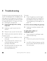
Page 33: ... not added first in the web app The prerequisite for network scan is that the gateway must be correctly connected Maintenance data will only be read out if a network scan was executed beforehand Remedy f f Place the gateway in service again and pay attention to the sequence of installation steps see chapter 4 Commissioning and setting up on page 16 8 2 Error when adding the gateway 4 4 Gateway can...

Page 34: ...ort on page 46 8 3 Error when connecting the gateway 4 4 Gateway button B flashes at regular intervals B 4 4 A connection cannot be established 4 4 An error message appears in the web app Possible causes No LAN connection or faulty LAN connection Router has no connection to the Internet WI FI settings are not correct or complete Remedy 1 Return gateway to default state see chapter 5 1 Gateway rese...

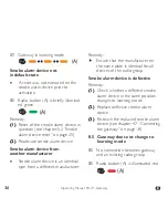
Page 35: ... A is illuminated red A Smoke alarm device incorrectly positioned Smoke alarm device is installed too close or too far away from other smoke alarm devices Remedy 1 Return smoke alarm device to de fault state see chapter 5 2 Smoke alarm device reset on page 25 2 Correct the position of the smoke alarm device 3 Activate smoke alarm device 5 5 Smoke alarm device in learning mode Radio group no longer...

Page 36: ... manufacturer Smoke alarm device is an identical type from a different manufacturer Remedy f f Ensure that the manufacturer on the name plate is identical for all devices of the radio group Smoke alarm device is defective Remedy 1 Check whether a different smoke alarm device in the same position changes to learning mode 2 Replace defective smoke alarm device 3 Re teach the replaced smoke alarm dev...

Page 37: ... will be switched off after 10 minutes Remedy f f Bring the radio group into learning mode see chapter 6 4 Installation of the gateway in an existing radio group on page 26 Maximum number of smoke alarm devices Radio group already contains the maximum number of smoke alarm devices Remedy f f Reinstall radio group with a lower number of smoke alarm devices Gateway not in default state Radio module ...

Page 38: ...Start learning mode on the gateway A A A 5 5 Gateway detects the radio group and is in learning mode for another 10 minutes 4 Briefly press radio button A on the gateway Signal LED of radio button A Off 5 5 Radio group is extended Gateway is defective Remedy 1 If it was possible to establish the connection to the gateway but the measures cited above do not func tion contact customer support see ch...

Page 39: ...ally see chapter 4 13 Switching off the gateway on page 24 Remedy f f No additional measures are required Gateway damaged Gateway shows possible external damage see chapter 2 4 General safety information on page 10 Remedy 1 Replace damaged gateway 2 Reinstall the chapter 4 Com missioning and setting up on page 16 replacement device accordingly 3 Dispose of old device see chap ter 10 1 Disposal on ...

Page 40: ...Check Internet connection of the router 3 Restore power supply 4 Restart router 5 Replace router if necessary see FAQ WI FI connection to the router is faulty WI FI error e g after a power outage or due to changed WI FI settings Remedy 1 Check configuration of the router 2 Set up gateway connection again see chapter 4 6 Gateway setup on page 18 LAN connection to the router is faulty 4 4 Gateway bu...

Page 41: ...eway Cyclic acoustic signal on the gateway for 30 seconds B f f Press gateway button B until a longer acoustic signal is emitted then release B 5 5 Network function is reset If the long tone does not sound see chapter 8 8 Error at gateway reset on page 44 f f Reconnect gateway see chapter 4 7 Connecting the gateway on page 18 3 If the error persists reset and re in itialize all smoke alarm devices...

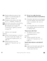
Page 42: ...Connection to gateway lost on page 29 2 Repeat network scan see chapter 4 9 Network scan on page 21 8 7 Error in a radio function smoke alarm device reachability 4 4 Procedure network scan test signal firmware update read maintenance data is concluded with an error message 4 4 A wrong response or no response from specific smoke alarm devices or radio groups Temporary radio fault Interference due t...

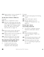
Page 43: ...Dispose of old device see chap ter 10 1 Disposal on page 45 Not with the smoke alarm device connected to the radio group A smoke alarm device has indeed been installed but not integrated in the radio group Remedy 1 Bring the radio group into learning mode 2 Add smoke alarm devices 3 Repeat network scan see chapter 4 9 Network scan on page 21 Smoke alarm device incorrectly positioned Excessive or i...

Page 44: ...Ensure that you maintain the pressure point of the gateway button B 9 Maintenance 9 1 Maintenance You must perform visual and function tests at regular intervals Software update As a rule the software of the gateway is updated at regular intervals see FAQ Visual inspection and function check Perform a visual inspection once a month Ensure that The Power cable and the power unit are undamaged and c...

Page 45: ...he following when cleaning f f Clean with care e g with a damp cloth f f Do not press the radio button A or the gateway button B by mistake 10 Decommissioning 10 1Disposal This product should never be placed in domestic waste according to the German Electrical and Electronic Devices Act ElektroG f f Return the device to be disposed of to the manufacturer for further utilization or hand it over to ...

Page 46: ...in screen of the web app pyrexx com de support 12 Glossary Radio network The total number of shared radio groups and subgroups in the connection with a gateway Learning mode In this status gateway and smoke alarm device learn which devices are members of a radio group Network scan The network scan scans all members of a radio network and allocates the devices to the gateway In this process it read...

Page 47: ...ency power supply duration 3 6V NiMH AA LSD NTC interchange able at least 2 hours Power supply 5V 1 A USB power supply unit 32 bit processor 32 bit SMD technology Optimum storage temperature 5 to 35 C 70 rel humidity Protection class IP 40 Colour Refrigerator white Material ABS Dimensions L x W x H 10 x 10 x 3 6 cm Weight Approx 210 g net Operation Web app Update capability Via WI FI and LAN ...

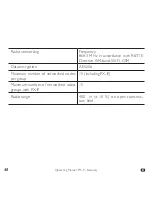
Page 48: ...uency 868 3 MHz in accordance with R TTE Directive ISM band WI FI GSM Data encryption AES256 Maximum number of networked nodes per group 15 including PX iP Maximum number of networked radio groups with PX iP 15 Radio range 400 m 10 on open transmis sion field ...

Page 49: ...val Alert tone commissioning and setup Power cable un plugged from gateway 30 seconds Network plug removed or power failure 60 seconds Network reset successful No interval 2 seconds Lastly 1 second continuous tone 1 second Start can take up to 2 minutes 1second continuous tone Moderately loud Moderately loud Moderately loud ...

Page 50: ... PyrexxTechnologies GmbH k_90706 Revision of the brochure 2016 03 Impressum Pyrexx Technologies GmbH Spichernstraße 2 10777 Berlin Deutschland Germany ...

Reviews: