background image

13

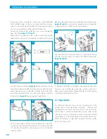
4.


Using the white 1/4” tube, 

exploded


view No. 6 on flap

, con-

nect the tap with the connector marked “faucet-grifo”. Prior to 
this cut the tube to the required length.

           In order to carry out all of the connections, foresee a longer tube,  
       so as to facilitate the movement of the system once installed, 
without out having to disconnect unnecessarily or make access to the 
same more difficult.

Carry out the connection of the tap via inserting the metallic 
nut, biconic and through the end of the 1/4” tube. 

Images 25 

and 26. 

Introduce the end of the tube into the interior of the tap 

connector and screw the nut using the T-bar or until you are 
sure it has been connected properly.
Carry out the connection to the system in the connector  
marked “faucet-grifo”
Unscrew the nut from the connector, remove the protector, 
introduce the screw into the end of the 1/4” tube coming out 
of the tap and screw it into the connector of the system. 

Image 

27.

480

365

190

280

450

FAUCET

robinet

Hahn

GRIFO

6.  Installation of the system


1.


Once it has been decided whether to put the tap on the 

counter top or sink (usually in the corner), a hole is drilled in  
the same with the 12 mm bit, to pass the connecting pipe 
through


Image 21.

Use the metal escutcheon to choose the location of the drill. 
If the metal escutcheon of the tap creates any difficulty in its 
assembly due to the geometrics of the counter-top or fridge, 
use the rubber joint supplied instead of the metal escutcheon 
in order to assemble the tap.


Choose the bit and the type of drill that is appropriate for the material 


in question.

2.


Prior to this, insert the metal escutcheon and a thick flat  

rubber joint into the connecting pipe (these must be on 
the upper part of the counter-top). Then pass the threaded  
connecting pipe through the hole. Once this is done, on the 
bottom end of the connecting pipe you connect: the rigid  
plastic washer, the grower washer and the hexagonal nut.
They should be tightened together with the No. 14/15 mm 
square wrench, until the tap is completely static and properly 
positioned.
The tap will be positioned as required after the final tightening 
(it is recommended that the tap handle is orientated towards 
the exterior of the counter top). 

Image 22.

 If the counter-top is 

thicker than that of the connecting pipe of the tap, you can use 
the tap extension (Ref. 261900). Finally, cut the left over part 
of the wide flat joint with a cutter in relation to the escutcheon. 

Image 23.

3.


Choose the location of the system and also foresee the 

space required for the reservoir tank. 

Image 24.


Fix the system to the wall using the brackets of the lower part 
of the same and the proper screws.
It is recommended that the cups are situated on the floor,  
with the objective of not straining the cupboard wall once the 
system is filled with water.

6. Installation of the system

21

22

24

23

27

26

25

exploded view No. 6 on flap

Summary of Contents for PROLINE PLUS

Page 1: ...INSTRUCTIONS MANUAL PROLINE PLUS PROLINE PLUS PUMP ...

Page 2: ...trol system for lower water consumption MANUAL FLUSHING VALVE Manual valve for the washing of the membrane SOLENOID VALVE With safety filter DIRECT ACCESS Easy maintenance INSERT Safety system in the pipe connections MANUAL FLUSHING VALVE Manual valve for the washing of the membrane DIRECT ACCESS Easy maintenance INSERT Safety system in the pipe connections ProlinePlus PUMP ...

Page 3: ...3 ...

Page 4: ...p Store tap Low pressure switch High pressure switch Granulated carbon post filter Membrane container 24 V electro valve with mesh filter UP7000 24 Vdc pump Metallic structure depending on model 5 μm sediment filter Activated granulated carbon cartridge GAC Activated granulated carbon cartridge BLOCK KEY a b c d e f g h i j k l m n DESCRIPTION 5 μm sediment filter Activated granulated carbon cartr...

Page 5: ...or the proper working of the system 05 2 Installation of the system 05 3 Operation and maintenance 05 4 Use of the system 05 5 Recommendations for the correct use of the reverse osmosis water 06 INSTALLATION OF THE SYSTEM 07 OPERATION OF THE PROLINE PLUS SYSTEMS 07 1 Description of Operation 08 MAINTENANCE AND CONSUMABLES 08 1 Maintenance 08 2 Hygienisation 08 3 Flushing 9 IDENTIFICATION GUIDE AND...

Page 6: ...ibuted by natural osmosis The human body is mainly made up of water Woman 55 65 Man 65 75 Child 80 An adult body contains between 38 and 48 litres of water 30 of which is found in the cells This water in the body which is almost completely recycled every 15 days is the basis for the transportation of nutrients oxygen to cells the elimination of waste and it controls the body temperature We consume...

Page 7: ...stances reduced by the reverse osmosis membrane The chemical composition and concentration of salts and other substances of the water on entering the reverse osmosis system has an affect on the purified water The TFC reverse osmosis membrane of your PROLINE PLUS Series system can reduce the concentration of the elements and compounds among others outlined in the following tables ELEMENT COMPOUND O...

Page 8: ... 20 5 80 BY PRESSURE ON PRODUCTION 0 70 0 25 0 33 0 42 0 58 1 00 1 08 1 17 1 25 1 42 REJECTION OF SALTS 84 88 90 92 93 95 95 95 95 CONVERSION FACTOR CONVERSION FACTOR BY TEMPERATURE TemperaturE ºC 6 8 10 12 14 16 18 20 22 25 28 30 32 34 ON PRODUCTION 0 38 0 45 0 52 0 59 0 66 0 70 0 77 0 85 0 88 1 00 1 09 1 16 1 23 1 30 The life of the membrane is evaluated by the percentage of salts rejected 90 95...

Page 9: ...PRODUCTION LPD 150 MEMBRANE Type 1 x 1812 50 MEMBRANE PRODUCTION 175 LPD Soft water with 250 ppm T 25 ºC Recovery 15 Pressure against membrane 3 4 bars without counter pressure PUMP Booster MAX ACCUMULATION pre charged tank at 7 PSI 19 litres ELECTRIC CURRENT 220 240 V 50 Hz 24 W ELECTRIC ADAPTOR 100 240 V 50 60 Hz 24 Vdc 1A MANUFACTURER Manufactured by Puricom Water Ind Corp Taiwan for PURICOM EU...

Page 10: ... higher than 2000 ppm contact your distributor It is recommended that you soften the water to be treated or that has a maximum hardness of 15 ºF with the objective of obtaining the optimum performance of the system Should the water to be treated have a level of hardness superior to 15 ºF the life of the membrane may be reduced and also the performance of the system It is recommended that you brush...

Page 11: ... electrical socket that is at least 1 metre away The location foreseen for its installation must have sufficient space for the machine itself its accessories connections and to carry out maintenance comfortably Under no circumstances must the system be installed outdoor The systems should not be installed next to a heat source or where it receives a direct flow of hot air dryer refrigerator etc Th...

Page 12: ... by qualified personnel from an authorised technical service Follow the recommendations in Section 5 of this manual Given that the appliance that you are going to install improves the quality of the water that you are going to consume and is considered a food all of the tools that you are going to use for the assembly and installation must be clean and under no circumstances contaminated or impreg...

Page 13: ...sembly due to the geometrics of the counter top or fridge use the rubber joint supplied instead of the metal escutcheon in order to assemble the tap Choose the bit and the type of drill that is appropriate for the material in question 2 Prior to this insert the metal escutcheon and a thick flat rubber joint into the connecting pipe these must be on the upper part of the counter top Then pass the t...

Page 14: ...s properly assembled and water tight Subsequently in the male connector of the 1 2 adapter connect the flexible pipe usually female Should it be necessary to install a special component it should not be iron or contain iron components as on rusting these can reduce the performance of the appliance To ensure the proper installation and water tightness of the connections made open the right angle en...

Page 15: ...pe collar shall be assembled but making sure that the hole that you have made is completely aligned over the front part of the 1 4 connector part where the square pad goes done by putting the bit used for making the 6 mm hole there through the hole there is between the clamp and the drainpipe thereby avoiding any obstacle to the passing of water towards the same Put the nuts in the socket on the b...

Page 16: ... te Ref 279300 for every extra pipe connection you need 11 Check that the pressure of the reservoir tank is 0 5 bars 7 P S I using the portable pressure gauge and the valve that is at the bottom of the tank If this is not the case fill or empty the pressurised tank until you achieve the indicated pressure Image 40 6 Installation of the system ...

Page 17: ...h manual wash valve Connection to the drain Check valve Manual valve of reservoir tank Pressurised reservoir tank Activated carbon post filter Counter top tap Low pressure switch Shut off electro valve Booster pump High pressure switch 7 OPERATION OF THE PROLINE PLUS SYSTEMS Electrical diagram of proline plus pump VALID LIST FOR PROLINE PLUS PUMP AND PROLINE PLUS PROLINE PLUS PUMP 24 Vdc MOTOR PUM...

Page 18: ...valve 15 when this situation is detected The wa ter pressure against the membrane makes the reverse osmosis process possible On the one hand the reverse osmosis water after going through a check valve 9 is stored in a reservoir tank 11 and on the other hand the water with excess salts and unwanted substances go to the drain 8 for their elimination through the flow limiter 7 When the reservoir tank...

Page 19: ...has not been consumed for more than a month MAINTENANCE RECOMMENDATIONS BY YOUR OFFICIAL PROLINE PLUS SERIES DISTRIBUTOR NOTE The membrane must be substituted if a specific compound is higher than the maximum advisable permitted limit for drinking water European directive 98 83 EC An excess of a compound total chlorine turbidity hardness etc can lead to a reduction in the life of the filters and c...

Page 20: ...cing the 1 4 exit tube Connect this tube using its 1 4 nut of the exit of the post filter 6 Extract the membrane from inside the membrane housing images 82 and 83 and apply the hygienisation procedure de scribed in section 7 Start up and hygienisation Use the membrane housing wrench to disassemble the top and the vice grip pliers to extract the interior membrane Images 84 and 85 7 Replace the filt...

Page 21: ...elements and they will be eliminated down the drain For this after the continuous extraction of more than 2 litres of water image 86 open the 15 cleaning valve manually and close it immediately afterwards Images 87 88 and 89 By this simple action you are able to prolong the life of your membrane 8 Maintenance and consumables 86 88 87 89 opened CLOSED ...

Page 22: ...on in the in let valve or substitute it They are tightened too close to the wall Do not have holding pins They are in bad condition substitute them or not pushed into connectors enough Wait until supply returns Check condition of coil and clean it Change it if necessary Change filter Change membrane Check condition of restrictor If blocked clean or substitute Clean or substitute Check supply in th...

Page 23: ...gm in bad condition Transformer in bad condition SOLUTION Check if rejection stops with the reverse osmosis system unplugged Should it not clean or substitute Put in a pressure regulator Check that there is 0 5 Kg cm2 or 7 PSI air pressure with an empty tank Substitute Check regulation and where applicable substitute Clean if dirty If in bad condition substitute it Substitute Repair product or sub...

Page 24: ...N COMPLETE MAINTENANCE REPAIR HYGIENISATION OTHERS COMPLETE MAINTENANCE REPAIR HYGIENISATION OTHERS COMPLETE MAINTENANCE REPAIR HYGIENISATION OTHERS COMPLETE MAINTENANCE REPAIR HYGIENISATION OTHERS COMPLETE MAINTENANCE REPAIR HYGIENISATION OTHERS COMPLETE MAINTENANCE REPAIR HYGIENISATION OTHERS ...

Page 25: ...outside specifications provided or in those cases where it has been modified or prepared by personnel that do not belong to the company or official The substituted parts under guarantee remain the property of PURICOM EUROPE The term of the guarantee starts on the date of purchase of the system in your PURICOM EUROPE Distributor For whatsoever claim under the guarantee you are required to provide r...

Page 26: ...py them him herself to the GUARANTEE CERTIFICATE SHEET The installer distributor must keep this sheet and Ionfilter may request it with the objective of improving the post sales service and customer service to the client The technician carrying out the installation and putting the equipment into operation must have the appropriate technical capacity S O P N S N INFORMATION CONCERNING THE APPLICATI...

Page 27: ...27 ...
Page 28: ...allès Barcelona SPAIN puricom puricom eu www puricom eu Ref 584701 Manual de instrucciones PROLINE PLUS 2014 The quality system of Puricom Europe for the marketing and assembly of water treatment equipment and in accordance with regulation UNE EN ISO 9001 2000 8 435291 802972 ...

Reviews: