15
7.
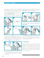
Make the connection of the reservoir tank and the con-
nector of the machine marked “tank/depósito” using the 1/4”
tube. To do this, put Teflon on the connector of the tank and
screw on, over this, the right-angle valve
exploded view No.12
on flap and image 36.
Connect the 1/4” tube to said right-an-
gled valve.
Image 37.
You should connect the other end of the 1/4” tube to the con-
nector of the machine marked “tank/depósito”.
Image 38.
8.
If necessary a socket shall be put in near to the machine
(< 1 m) for the electrical feed of the same, according to the
National legislation in force (only in the PROLINE PUMP PLUS)
image 39
.
9.
Make sure that all of the connections have been screwed
in properly.
Remember that when the pressure is superior to 3 kg/cm
2
, a
pressure regulator should be inserted into the feed tube to the
machine (Ref.577603), set at a pressure of 2.5 kg/cm
2
.
not obstruct the hole or water flow outlet). Envisage the
space necessary for the assembly of the clamp,
image 33
.
Next the drainpipe collar shall be assembled, but making sure
that the hole that you have made is completely aligned over
the front part of the 1/4” connector (part where the square
pad goes), done by putting the bit, used for making the 6 mm
hole there, through the hole there is between the clamp and
the drainpipe; thereby avoiding any obstacle to the passing of
water towards the same.
Put the nuts in the socket on the bottom part of the clamp and
afterwards put in the corresponding screws. The nuts must be
screwed in carefully and progressively, alternating between the
two. Try not to force the components.
Image 34.
The 1/4” tube must be connected, between the thread of the
drainpipe clamp and the connection of the machined marked
“drain-desagüe”,
image 35
.
Use the wrench to ensure that the tube in the nut of the drain-
pipe clamp is tightened properly (for the proper positioning of
the tube in relation to the nut, this should stick out of the front
part of the same some 2 mm).
Remember flushing valve must remaind closed!!
6. Installation of the system
34
exploded view No. 12 on flap
33
DRAIN
Abwasser
DESAGÜE
35
39
40
TANK
reservoir
Produktwasser
DEPÓSITO
38
37
exploded view No. 3 on flap
36
88
89
OPENED
CLOSED
Summary of Contents for PROLINE PLUS
Page 1: ...INSTRUCTIONS MANUAL PROLINE PLUS PROLINE PLUS PUMP ...
Page 3: ...3 ...
Page 27: ...27 ...


