4-7
Section 4
Electrical System
OS 385
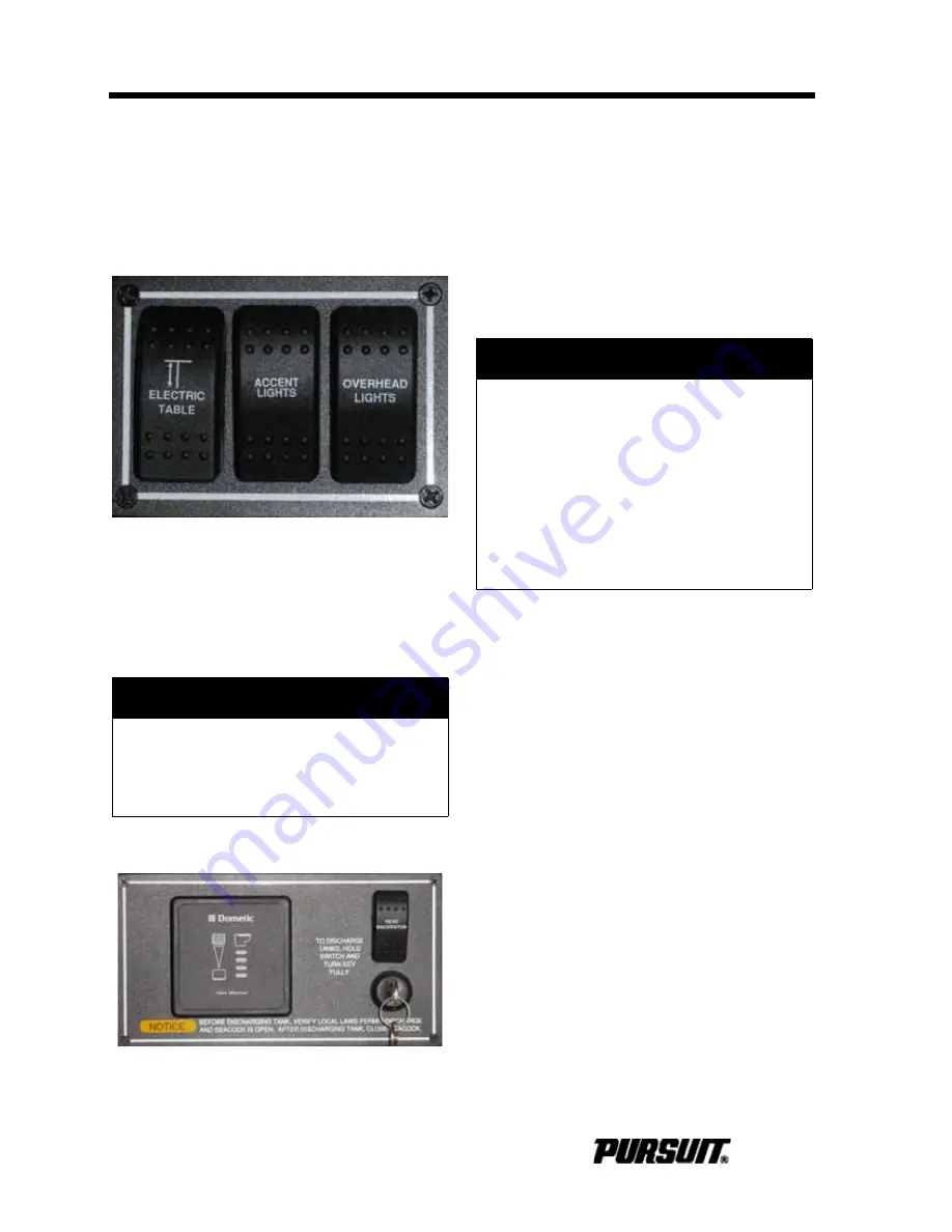
Cabin Switch Panels
Switches on the cabin panels operate the
interior and accent lighting for the cabin.
These panels are located at the cabin
entrance, forward on the head bulkhead, at
the entrance to the aft berth and inside the
head compartment.
Electric Table
The Electric Table switch on this panel
raises and lowers the V-berth table.
wARNWaG
Head Panel
The indicators on this panel display the hold-
ing tank level and also includes the holding
tank overboard discharge macerator switch.
The macerator switch can only be activated
when the key switch is fully turned. Refer to
Head Compartment of the Interior Equip-
ment.
4.4 AC System
The AC electrical system operates on a 240
volt, 50 amp, 60 cycle system. Models with
CE designations operate on a 230 volt, 32
amp, 50 cycle system.
The AC system is fed by the shore power or
by the generator. Your boat is equipped with
an isolation transformer. The isolation trans-
former maintains correct AC polarity regard-
less of the polarity of the shore power supply
and eliminates the need for a galvanic isola-
tion system and a reverse polarity indicator.
Refer to the isolation transformer manual for
additional information.
The main breakers in the AC Main Distribu-
tion Panel (AC MDP) are equipped with a
selector slide to prevent the shore power
source and the generator source from being
energized simultaneously and damaging the
electrical system components. These
breakers protect the system and compo-
nents from an overload. All AC current is
distributed to the AC components through
individual 120V/240V (230V for CE) circuit
breakers located in the AC MDP.
!
WARNING
To prevent serious injury or property
damage, clear obstructions around
the table before operating the switch
to raise or lower the table.
Cabin Panel (Typical)
Head Panel
!
DANGER
ELECTROCUTION, FIRE OR
EXPLOSION HAZARD
Contact with live wires or working on
an energized electrical system can
cause electrocution. It can also cause
sparks, resulting in fire and/or explo-
sion. Both cases will result in death or
serious injury. DO NOT work on an
energized system or allow unqualified
personnel to work on the system.
Summary of Contents for OS 345
Page 2: ......
Page 4: ...Operator Notes OS 375...
Page 16: ...12 Operator Notes OS 385...
Page 32: ...3 6 Operator Notes OS 385...
Page 34: ...4 2 Section 4 Electrical System OS 385 Main Distribution Panel MDP...
Page 54: ...5 8 Operator Notes OS 385...
Page 56: ...6 2 Operator Notes OS 385...
Page 98: ...12 6 Operator Notes OS 385...
Page 104: ...A 6 Operator Notes OS 385...
Page 106: ...B 2 Appendix B Maintenance Log OS 385 Date Hours Dealer Service Repairs Maintenance Log...
Page 107: ...Maintenance Log B 3 Appendix B OS 385 Date Hours Dealer Service Repairs...
Page 108: ...B 4 Appendix B Maintenance Log OS 385 Date Hours Dealer Service Repairs...
Page 109: ...Boating Accident Report C 1 Appendix C OS 385 Boating Accident Report...
Page 110: ...C 2 Appendix C Boating Accident Report OS 385...
Page 111: ...Float Plan D 1 Appendix D OS 385 Float Plan...
Page 112: ...D 2 Operator Notes OS 385...
Page 116: ...E 4 Operator Notes OS 385...
Page 117: ...Schematics F 1 Appendix F OS 385 Schematics...
Page 118: ...F 2 Appendix F Schematics OS 385...
Page 119: ...Schematics F 3 Appendix F OS 385...
Page 120: ...F 4 Appendix F Schematics OS 385...
Page 121: ...Schematics F 5 Appendix F OS 385...
Page 122: ...F 6 Appendix F Schematics OS 385...
Page 123: ...Schematics F 7 Appendix F OS 385...
Page 124: ...F 8 Appendix F Schematics OS 385...
Page 125: ...Schematics F 9 Appendix F OS 385...
Page 126: ...F 10 Appendix F Schematics OS 385...
Page 127: ...Schematics F 11 Appendix F OS 385...
Page 128: ...F 12 Appendix F Schematics OS 385...
Page 129: ...Schematics F 13 Appendix F OS 385...
Page 130: ...F 14 Appendix F Schematics OS 385...
Page 131: ...Schematics F 15 Appendix F OS 385...
Page 132: ...F 16 Appendix F Schematics OS 385...
Page 133: ...Schematics F 17 Appendix F OS 385...
Page 134: ...F 18 Appendix F Schematics OS 385...
Page 135: ...Schematics F 19 Appendix F OS 385...
Page 136: ...F 20 Appendix F Schematics OS 385...
Page 137: ...Schematics F 21 Appendix F OS 385...
Page 138: ...F 22 Appendix F Schematics OS 385...
Page 139: ...Schematics F 23 Appendix F OS 385...
Page 140: ...F 24 Appendix F Schematics OS 385...
Page 141: ...Schematics F 25 Appendix F OS 385...
Page 142: ...F 26 Operator Notes OS 385...
Page 143: ......
Page 144: ......


