105
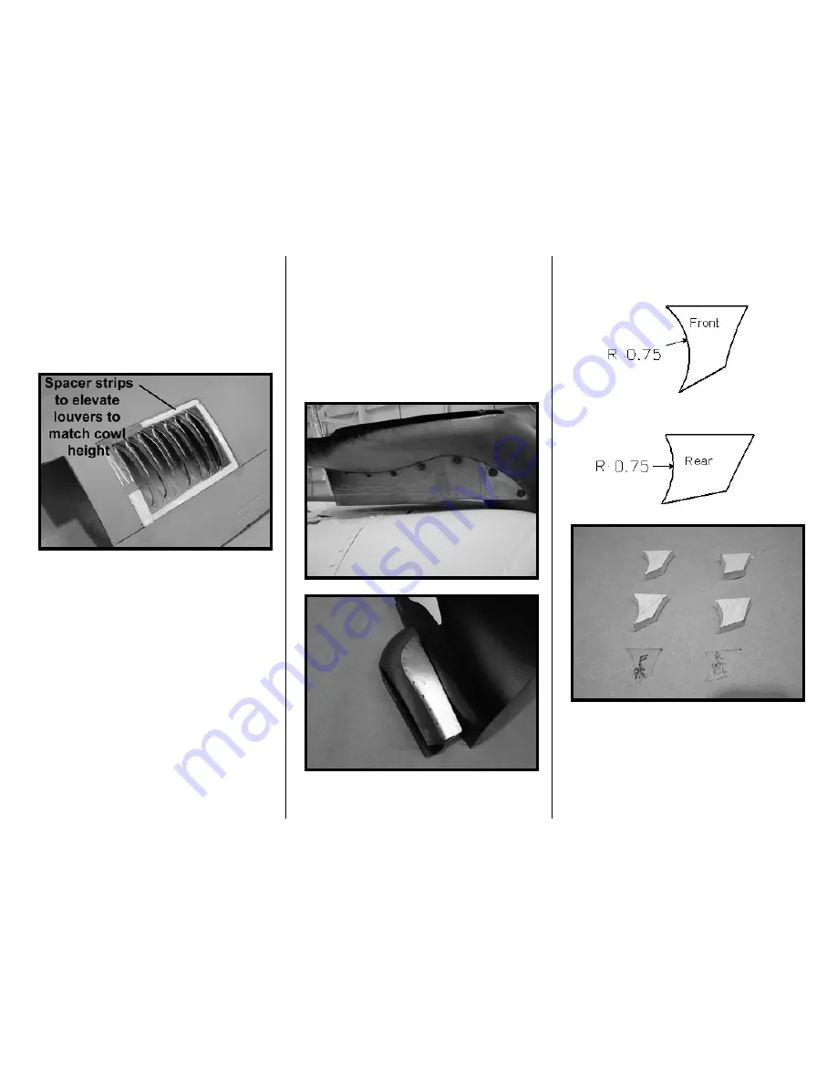
cowl, so you may need to CA in some
plastic strip spacers to elevate the
louver to match the outer surface of the
cowl.
8. Once the surfaces are even, CA in
the louver.
Exhaust Stacks:
For a sturdy mount, you will be securing
the exhaust stacks to the upper cowl.
We encourage you to use one of these
stacks as your muffler’s exhaust outlet,
but there are some considerations. The
supplied stacks are molded PVC so you
will need to shield the critical portions of
the stack from the exhaust heat. We
have found thin pieces of G-10 screwed
to the inside of the stack works well.
Alternatively, you can get a metal
exhaust stack at a hardware store – look
for a 1.5” dia. “wall tube” in the plumbing
section. You can also purchase an
optional, pre-cut metal exhaust stack
from us for $12 each.
There are a few critical alignments to
make before you bolt it on. To give you
an idea of what you’re re-creating, here
is a picture of the full-size stack from the
bottom and our prototype model’s left
exhaust stack.
1. Begin by making the support ribs
from ¼” scrap balsa (two per side).
Tracing the outlines below onto a clear
plastic template helps this task.
The ribs are slightly oversized to allow
for final adjustments. The alignments
for the stacks are as follows.
Rear Edge: Needs to be 1 1/8” from the
cowl.
Summary of Contents for T-34C TURBO MENTOR
Page 190: ...191 This Page Intentionally Left Blank ...
Page 191: ...192 Fin Rudder Template ...
Page 192: ...193 This Page Intentionally Left Blank ...
Page 193: ...194 ...
Page 194: ...195 This Page Intentionally Left Blank ...
Page 195: ...196 Laser Cut Parts Diagram ...


