149
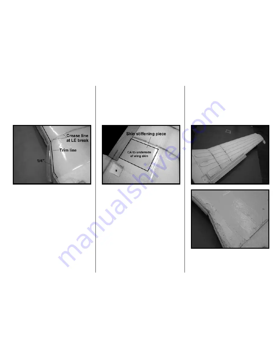
The root should be cut to maximize the
usable material (just remove the
flashing). The LE should be cut back ¼”
from the wing’s LE. Position the skin in
place and trace its edge at the root, LE
and tip so you know where to spread the
adhesive.
6. There is an area on the top wing skin
that usually produces a surface wave
that is larger than desired. This area is
near the root’s TE and best defined as
the scale walkway area behind the
molded spar detail and forward of the
ply TE support. This area is devoid of
molded detail, and thus susceptible to
waves. To offset this, cut a piece of
.010” or.020” scrap polycarbonate the
size roughly shown below and mark its
outline on the wing. This will become a
skin stiffening piece.
Remove the film from the underside of
the wing skin and all film from the scrap
piece. Sand each area where the
pieces will make contact. Apply ample
CA to the piece and position onto the
underside of the wing skin. Press the
piece firmly on a flat surface while the
CA cures. This will firm up the area and
minimize the likelihood of surface
waves.
7. The top wing skin will require a small
extension at its tip end. First, trim the tip
skin (near where you rough trimmed it)
with a straight edge. Cut a piece of
scrap .010” polycarbonate as long as
the tip skin (cordwise) and about 2” wide
– cut its mating edge with a straight
edge too. Make a joiner strip from scrap
polycarbonate as long as the tip and
about ¾” wide. Remove the film from
the extension and joiner pieces. Sand
the mating areas of all skins. Butt the
extension piece next to the wing tip with
the bottom side up. Apply CA to the
edges of the joiner strip and position it
across the joint.
8. Apply adhesive as shown below.
The top of the wing will be exposed to
significant heat from the sun so you
want to have sufficient adhesive. After
spreading the adhesive even over the
wing you may still have a need to apply
more adhesive for sufficient coverage.
Summary of Contents for T-34C TURBO MENTOR
Page 190: ...191 This Page Intentionally Left Blank ...
Page 191: ...192 Fin Rudder Template ...
Page 192: ...193 This Page Intentionally Left Blank ...
Page 193: ...194 ...
Page 194: ...195 This Page Intentionally Left Blank ...
Page 195: ...196 Laser Cut Parts Diagram ...


