20
Temporarily thread the stab retaining
bolt through the stab from the top so
that it protrudes into the cavity you just
made. Center a one inch square piece
of 1/8” thick ply over the cavity and
press it down onto the bolt so that a light
impression is left where the bolt is. Drill
a 5/32” hole in the ply at the impression.
Apply CA to secure the ply in the cavity
with the bolt centered in the drilled hole.
To secure the stab from here on out,
you will insert the bolt from the bottom
surface.
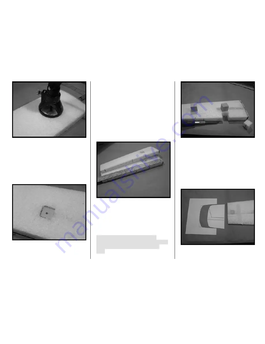
17. The stab’s hinge locations will
require balsa blocks to provide for a
solid mounting of the Robart® Point
Hinges (you will be doing this task for all
other hinge locations too). Start by
marking the hinge locations on the
stab’s TE. The scale placement of the
hinges are at approximately 4”, 7.5” and
14” from the root.
Next, center a one inch square balsa
block at the hinge location on the stab’s
upper surface, then trace its outline on
the stab. Use an X-acto knife to cut out
the foam. Using CA, glue the balsa
blocks into the stab.
Tip: Level either the top or bottom
surface of the block even with the stab –
that way you only have to sand one
side.
Sand down the protruding block side
even with the stab.
18. Cut out the stab’s tip shape
template from Appendix A at the end of
this manual. Tape the stab to its EPP
middle strip (the scrap foam from
between the stab and the elevator) and
the EPP elevator.
Summary of Contents for T-34C TURBO MENTOR
Page 190: ...191 This Page Intentionally Left Blank ...
Page 191: ...192 Fin Rudder Template ...
Page 192: ...193 This Page Intentionally Left Blank ...
Page 193: ...194 ...
Page 194: ...195 This Page Intentionally Left Blank ...
Page 195: ...196 Laser Cut Parts Diagram ...


