46
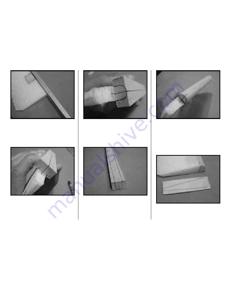
9. Mark a centerline on the LE. Also
mark the centerline of the rudder near
the top. Center the LE onto the rudder
and mark the location of the rudder’s
edges onto the LE as shown.
10. At the tip, draw a LE radius as
shown.
The radius at the root end is almost a
half circle in shape (see photo on next
page). Drawing lines connecting the
edges of the radii will help you to shape
the LE. Sand the LE to shape.
11. Epoxy the LE to the rudder aligning
their centerlines.
12. Trace the rudder’s bottom edge
onto scrap 1/8” ply. Draw additional,
parallel lines 1/16” inside those lines,
except at the LE radius. Cut the ply
along these inside lines and along the
LE radius. This ply plate will add rigidity
to the rudder’s control arm block.
The TE can be cut slightly short as
shown below. In this photo, the ply is
sandwiched between the rudder and the
Summary of Contents for T-34C TURBO MENTOR
Page 190: ...191 This Page Intentionally Left Blank ...
Page 191: ...192 Fin Rudder Template ...
Page 192: ...193 This Page Intentionally Left Blank ...
Page 193: ...194 ...
Page 194: ...195 This Page Intentionally Left Blank ...
Page 195: ...196 Laser Cut Parts Diagram ...


