8
Assembling the Fuselage
The first step in assembling the fuse is
for you to decide if you want a full depth
cockpit or to utilize the existing foam
false floor. If you’re going with the false
floor option, skip to Step 5 and disregard
cockpit instructions presented later in
the instructions.
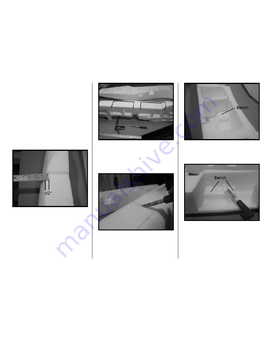
1. For full depth cockpits, mark cut lines
as shown: 1/2” from the top outside
edges and also, on the fuse centerline,
extend the instrument panel and cockpit
back surfaces to the fuse top.
2. Your fuse should be marked as
shown above. With a new X-acto blade,
cut along the lines. Cutting EPP with a
dull blade does not work well so make
sure the blade is sharp.
3. Next, cut the cockpits’ false floor
supports as shown below. Note the
bench where the scale, side instruments
go – retain this bench.
Getting a knife down into the cockpit can
be difficult so you can cut this support
away in sections.
4. Use a sanding block to level any
remains of the support. Alternatively, a
tool that we like to use is a Sure-Form
tool – it works faster.
Summary of Contents for T-34C TURBO MENTOR
Page 190: ...191 This Page Intentionally Left Blank ...
Page 191: ...192 Fin Rudder Template ...
Page 192: ...193 This Page Intentionally Left Blank ...
Page 193: ...194 ...
Page 194: ...195 This Page Intentionally Left Blank ...
Page 195: ...196 Laser Cut Parts Diagram ...


