


Nixie Tube Clock ‘Dink’
Issue 9 (10 November 2017)
www.pvelectronics.co.uk
- 13 -
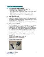
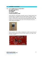
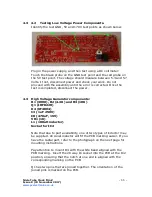
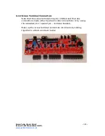
4.4 High Voltage Generator Test.
- Refer to the warnings on page 4
- Insert IC2 into its socket. Orient the notch on the IC with the
notch on the IC socket and the PCB marking.
Power up the PCB, and using the GND and 170V test points,
measure the high voltage generated. It should be initially 150-
190V. Using the VR1 brass screw, slowly adjust the screw until the
voltage is between 168 and 172V. Disconnect the power supply.
Finally, remove IC2 from its socket and replace on its static-
protective foam. It is best kept safe until later.


