


Nixie Tube Clock ‘Dink’
Issue 9 (10 November 2017)
www.pvelectronics.co.uk
- 9 -
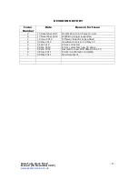
4.
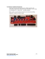
ASSEMBLY OF THE PCB
4.1
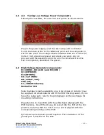
Low Voltage Power Components:
D1 and D3 (1N581x)
D5 (1N4148)
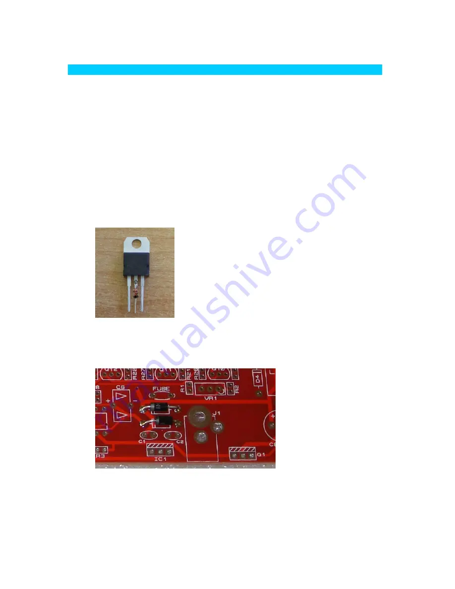
IC1 (7805)
C1 and C2 (100nF)
J1 (DC Connector), FUSE
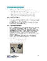
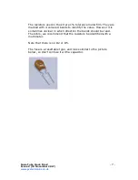
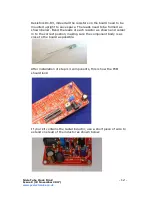
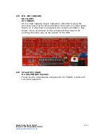
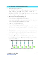
Parts bags from serial 0691 onwards require a 1N4148 diode to be
inserted into the middle leg of the 7805 voltage regulator. First,
clip the middle lead so it is 4-5mm long, then solder the diode as
shown. It can be then used as per the remaining instructions. But
please note, the photos in the rest of the instructions show the
7805 without this addition.
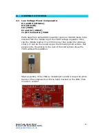
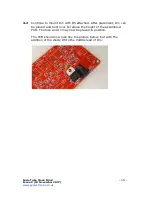
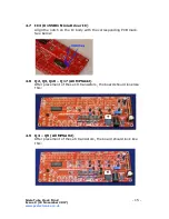
Start assembly of the PCB by installing D1 and D3. Align the white
band on the components with the band marked on the PCB. Then
mount C1 and C2.


