


Nixie Clock Kit ' Maestro’
ISSUE 5 (01 June 2018)
www.pvelectronics.co.uk
- 14 -
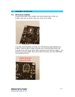
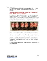
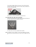
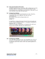
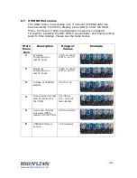
Then install the RGB LEDs from the back of the PCB, and solder
from the front of the PCB. Clip off the excess leads, probably just
from the two longer leads.
Now solder the remaining RGB LEDs in the same way.
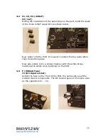
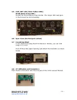
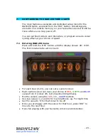
4.12 AM1, AM2, PM1, PM2 (4mm neon lamp)
Cut the clear heat shrink into eight lengths of 15mm and slip over
the neons leads then shrink with a hot air gun.
The four neons can now be soldered onto the PCB.
4.13
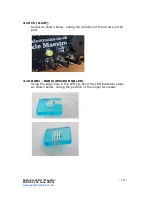
The Maestro is now complete. You can insert again the six tubes
and move onto the next section, to learn how to configure and use
it.


