background image

Nixie Clock Kit ' Maestro’ 


ISSUE 5 (01 June 2018)


www.pvelectronics.co.uk


- 20 - 

6.  

XTERNA FUNCTIONS 


6.1


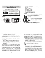
About the XTERNA Module 

XTERNA is our new concept for synchronising time and capturing 
outdoor temperature for display on our clock and thermometer 
kits. Driven by a PIC microcontroller with advanced low power 
modes, the XTERNA captures time from GPS satellites every 6 
hours, and stores in an on-board Temperature Controlled Crystal 
Oscillator (TCXO). Further, the device captures outdoor 
temperature every 10 minutes from an on-board DS18B20 digital 
temperature sensor. Every 10 minutes XTERNA transmits the time 
and temperature data, which can be received by our XTERNA 
compatible clocks.  

Additional data is transmitted such as battery voltage and GPS fix 
time.  

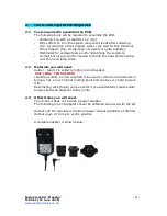
Supplied as a complete hobby kit of parts (For shipping reasons, 
batteries are not included), the kit takes approx 30-40 minutes to 
comfortably assemble. The TCXO IC is pre-soldered, so there is no 
fiddly SMD soldering to worry about.  

Naturally, XTERNA is sealed against rain ingress.  Battery life is 
estimated between 6 to 12 months. We recommend high quality 
branded batteries for the longest operation between battery 
changes. 

The module should be placed outdoors. But as close as possible to 
the indoor clock or thermometer and away from direct sunlight.


6.2


Specification


Working Temperature Range: -40 °C to +60 °C. (-40 °F to 
+140 °F) 
Typical Reception Range: 10 to 30 Metres (30 to 100 ft). 


6.3


Configuring for XTERNA Reception


Your Maestro Clock is configured by default for XTERNA reception. 
If you have changed your configuration settings, you need to set 
parameter 12 to value 5. Also parameters 14, 15, 16 need to be 
set to specify your location’s offset from UTC.  


Summary of Contents for Nixie Maestro

Page 1: ...Nixie Clock Kit Maestro ISSUE 5 01 June 2018 www pvelectronics co uk 1 Assembly Instructions and User Guide Nixie Clock Type Nixie Maestro ...

Page 2: ...Y Issue Number Date Reason for Issue 5 01 June 2018 New Version PCB 4 01 April 2017 New version with neons for AM PM 3 10 December 2014 Typing errors corrected Updated photos Added MSF and DCF support 2 27 December 2012 GPS Indicator LED function clarified 1 06 December 2012 New document ...

Page 3: ...ther DD MM YY or MM DD YY or YY MM DD format Programmable date display each minute Scrolling display of date or standard display Alarm with programmable snooze period Optional GPS XTERNA synchronisation with status indicator LED Dedicated DST button to switch between DST and standard time Supercapacitor backup Keeps time during short power outages Simple time setting using two buttons Configurable...

Page 4: ...tions if XTERNA module used Display of outdoor temperature in Celsius or Fahrenheit each minute Min Max temperature in last 24 hours Wireless Auto Sync of time from GPS with auxiliary TCXO GPS Sync time and time since last GPS Fix Voltage of XTERNA module battery Firmware version of XTERNA module ...

Page 5: ...enerated by this circuit can give a potentially LETHAL ELECTRIC SHOCK DISCLAIMER This product is supplied as a kit of parts intended only for suitably qualified electronic engineers who are suitably qualified and experienced in electronics assembly and are familiar with safe procedures for working with high voltages The supplier his agents or associates accept no liability for any damage injury or...

Page 6: ...r gun will be needed to shrink the heat shrink tubing over the neon lamp wires 2 2 Materials you will need Solder lead tin solder is highly recommended USE LEAD TIN SOLDER Lead free solder as now required to be used in commercial products in Europe has a much higher melting point and can be very hard to work with Desoldering wick braid can be useful if you accidentally create solder bridges betwee...

Page 7: ... PM2 4 500mA Fuse F 1 APA106 RGB LED RGB1 RGB6 6 2 way Right angle socket CY18 Module 2 CY18 Module Supplied if you ordered an XTERNA 1 Harwin Socket 66 20cm Wire for antenna 1 15cm Clear heat shrink 1 LED Bending jig 1 Self Adhesive insulating sheet 1 It is recommended that the kit is checked against the list above to ensure all parts are present before commencing assembly Don t be alarmed if the...

Page 8: ...ube location at a time as follows Be sure to insert from the front of the PCB You may need to push in firmly To hold them in place whilst you solder insert a IN 12 tube then flip over the PCB and solder the sockets from the back of the PCB Solder with minimum solder as soon as you see solder flow around the annulus you can withdraw the solder and iron ...

Page 9: ...s as shown below Now solder into the PCB It is easier to solder the top pads rather than the bottom pads Now also solder C4 in a similar manner with the white stripe matching the white cross hatching on the PCB 4 3 F 500mA Fuse J1 DC Input socket Solder the fuse on the front of the PCB the same side as all the surface mount components The DC Socket goes on the same side as the capacitors C1 C4 ...

Page 10: ...ith a support issue at this stage please be clear If you refer to a count down it will be very confusing and slow down your support query If you do not get this count up or have missing or overlapping digits stop and check your work Try swapping tubes around to see if the problem is with the tube or the location Please make these basic tests before contacting us for help and have the results to ha...

Page 11: ...longer LED Lead goes in the hole with a circle marking 4 6 Sync Conn Vertical jack socket 4 7 Insulating Sheet If you will not be using the CY18 Receiver module you can omit steps 4 7 to 4 8 Peel off the white paper backing and attach the insulation as shown below 4 8 CY18 Module and Connectors Push the two connectors onto the end pins of the CY18 receiver Module ...

Page 12: ...ly measure out exactly 17cm of the antenna wire cable strip off 2mm from one end and solder to the ANTENNA Pad This Antenna wire can be routed conveniently and neatly inside the final enclosure you make or buy 4 9 Piezo Buzzer LS1 and Push Button Switches Solder as shown below If you prefer you can only solder the 2 pads for each switch that are closest to the PCB edge The other 2 pads are not use...

Page 13: ...ectronics co uk 13 4 10 C5 0 22F Solder as shown below noting the direction of the arrows on the part 4 10 RGB1 RGB6 APA106 RGB LED Using the large hole in the LED jig bend the LED leads two steps as shown below noting the position of the longer two leads ...

Page 14: ...m the two longer leads Now solder the remaining RGB LEDs in the same way 4 12 AM1 AM2 PM1 PM2 4mm neon lamp Cut the clear heat shrink into eight lengths of 15mm and slip over the neons leads then shrink with a hot air gun The four neons can now be soldered onto the PCB 4 13 The Maestro is now complete You can insert again the six tubes and move onto the next section to learn how to configure and u...

Page 15: ...he seconds will become highlighted Continue holding the button a further 2 seconds until the clock displays in this format 00 XX 99 The 99 in the seconds digits tells you that you are in the configuration menu In configuration mode the hours digits diplay the current parameter being adjusted and the minutes digits display the current value stored against the parameter For each parameter and referr...

Page 16: ...ation left right 2 AM PM Indication left right flashing 3 AM PM Indication top bottom 4 AM PM Indication top bottom flashing 5 All slow flashing 6 Slow flashing left right 7 All flashing 8 Both illuminated 9 Railroad fast 10 Railroad slow 11 Colon neons during night dimmed mode 2 As per parameter 10 12 Radio time signal source3 0 to 3 reserved 4 GPS 5 XTERNA 13 GPS Baud rate 0 4 8 Kbps 1 9 6 Kbps ...

Page 17: ...etween 50 and 55 seconds past the minute 7 Press SET briefly during Night Mode to show time for prescribed period 8 Set this parameter to 1 to restore factory configuration settings Internal operations will then load all the original settings and restore the value to 0 1 Slots every minute 2 Slots every 10 minutes default 3 Slots every hour 4 Slots at midnight 23 Reserved 24 Reserved 25 Reserved 2...

Page 18: ...tton to set the hours Proceed in this fashion to set the calendar Year Month and Day Finally briefly Press SET again to revert to normal clock operation Showing Date From time display mode briefly press SET button Date will be shown for 5 seconds then revert to time display Auto Date Display Setting parameter 27 to 1 or 2 will enable auto display of date between 50 and 55 seconds past each minute ...

Page 19: ...data does not contain DST information so the DST status will need to be set manually in GPS sync mode as well as manual time set mode Calibration of Timekeeping Accuracy Over time you may observe the clock runs faster or slower than an accurate time standard You can finely adjust the timekeeping by setting configuration parameters 20 and 21 We recommend to precisely set the clock against a known a...

Page 20: ...ime Supplied as a complete hobby kit of parts For shipping reasons batteries are not included the kit takes approx 30 40 minutes to comfortably assemble The TCXO IC is pre soldered so there is no fiddly SMD soldering to worry about Naturally XTERNA is sealed against rain ingress Battery life is estimated between 6 to 12 months We recommend high quality branded batteries for the longest operation b...

Page 21: ...erature will not be displayed until after the first synchronisation Set Celsius or Fahrenheit using parameter 29 Fahrenheit 1 Celsius 2 Temperature is displayed between 30 and 35 seconds past each minute Celsius is displayed with 0 5 C resolution Fahrenheit is displayed with 1 F resolution Positive and negative temperature is indicated by the left hand neons Neon indicator PM2 acts as a decimal po...

Page 22: ...sequentially and finally exiting back to time display Please see the table below Stats Menu Item Description Range of Values Example 1 Minimum Temperature in last 24 hours 40 C to 60 C 40 F to 140 F 2 Maximum Temperature in last 24 hours 40 C to 60 C 40 F to 140 F 3 Voltage of XTERNA Battery 2 5V to 5 0V 4 Time required for last GPS fix loaded into the TCXO 0 to 98 sec 99 no fix at last attempt 5 ...

Page 23: ...effect at your choice of speed 7 1 Entering RGB LED menu Press and hold the DST button until the display shows 00 0 00 The first minutes tube will not be lit For each hour 0 23 you can set a custom colour Each custom colour can have your choice of RED GREEN and BLUE values from 0 colour off to 8 maximum brightness Mix the colours using the SET ADJ ALARM buttons Use low values 1 2 and 3 for low bri...

Page 24: ...ics co uk 24 Colours are displayed live during RGB menu In the example above between 8 and 9 hours the LEDs will be purple 8 red 0 green and 8 blue In the example below between 19 and 20 hours the LEDs will be blue with a hint of green 0 red 2 green and 8 blue ...

Page 25: ... hour The speed of the cycling will then be governed by the GREEN value 0 very slow change 9 very fast change This auto colour cycling mode is explained in the picture below Red 9 therefore Auto Colour Cycling is enabled for 12 13 hours Green 3 so speed is 3 Blue value has no effect Note The colours do not cycle live during Auto Colour Cycling setup The cycling starts only during normal time and d...

Page 26: ...ntence 8 1 Configuring for GPS Synchronisation Set parameter 12 to value 4 Set the baud rate in parameter 13 Set parameters 14 and 15 for the hours and minutes your time zone is offset from UTC Time This is usually only whole hours Set parameter 16 to identify whether the offset is minus 0 or positive 1 of the time source SYNC LED will light when the clock has received recent GPS or XTERNA synchro...

Reviews: