


Nixie Tube Clock ‘Nixie QTC-Four’
Issue 1 (1 December 2019)
www.pvelectronics.co.uk
- 7 -
3. LIST OF COMPONENTS
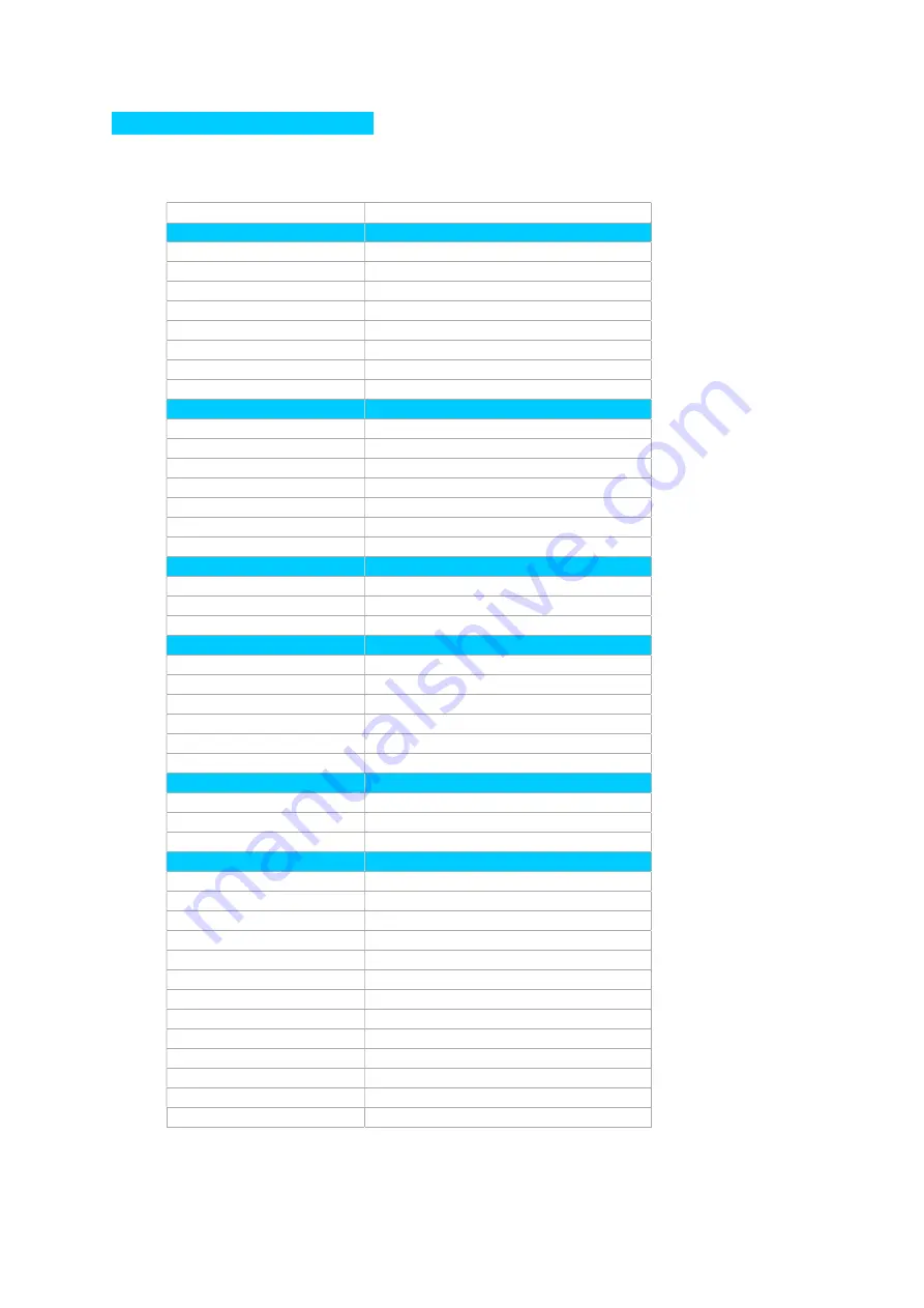
3.1 Table of Components – Driver Board
Circuit Designation
Part Description
Resistors
R1, R2
4.7 KΩ, ¼ Watt
R3
390 KΩ, ¼ Watt
R4
4.7 KΩ, ¼ Watt
R5 – R10
1 KΩ, ¼ Watt
R7 - R10
1 KΩ, ¼ Watt
R11 – R14
2.7 KΩ, ¼ Watt
R15, R16
4.7 KΩ, ¼ Watt
R17, R18
390 KΩ, ¼ Watt
Capacitors
C1, C2
220uF, 16-25V, Electrolytic
C3
1uF, 250V,
C4
220uF, 16-25V, Electrolytic
C5
15pF Ceramic
C6
33pF Ceramic
C7
100nF Ceramic
C8
0.1F or 0.22F
Transistors
Q1
IRFD220 MOSFET
Q2 – Q5
EL817 Optocoupler
Q6, Q7
MPSA42
Diodes
D1 – D3
1N5819
D4
1N4148
D5
UF4004
DST
5mm Yellow LED
SYNC
5mm Green LED
RGB1 – RGB4
APA106 RGB LED
Integrated Circuits
IC1
LM2576 SMD 5V voltage regulator
IC2
PIC16F1936 8-bit microcontroller
IC3
K155ID1 Nixie Driver
Miscellaneous
L1, L2
100uH inductor
AM, PM
4mm wire ended neon lamp
SET, ADJ
Miniature horizontal push button
IC2 Socket
28 Way narrow IC socket for IC2
IC3 Socket
16 Way narrow IC socket for IC2
Sockets for Q2 – Q5
8 Way narrow IC sockets
J1
2.1mm PCB power socket
GPS
Surface mount 3.5mm jack socket
FUSE
500mA fuse
Insulation
15 cm Clear insulation for neons
NX1 – NX4
2X6 way 0.1” header plug
DEKA
3 way Right Angle Male header
X1
32.768KHz watch crystal


