Operation and Maintenance Manual Rev M(ii) 4/03
- 22 -
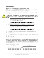
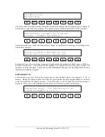
volume was outside acceptable parameters, the flow error screen appears. This screen is similar to the flow
data screen shown above. The board should be removed before returning the machine to operation.
NOTE: Any changes made to settings in the material delivery system (material pressure, stroke
adjustment, etc.) may affect the data from the flow monitor. If this happens, the operator may need to
determine the correct material volume again.
Flow Monitor Calibration
Periodically, the flow monitor calibration should be checked. Start by connecting a PC to the Dispensing
System, open a terminal screen and enter DEZ=0. This resets the flow monitor encoder to zero. Then
dispense 10 cubic centimeters of material through any valve, by means of a manual purge. When finished,
enter MG _DEZ on the terminal screen. This returns a value representing the number of encoder counts
read by the flow monitor. Calculate the flow monitor calibration value: (Encoder Counts / 10) = FC_CAL.
Change the value of the FC_CAL variable in the Machine-Specific Information section of the
Main
program to the result of the calculation.
NOTE: For a more precise calibration, determine volume by weight. The specific gravity or density of
the material must be known to do this.
Flow Control Mode
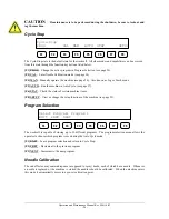
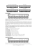
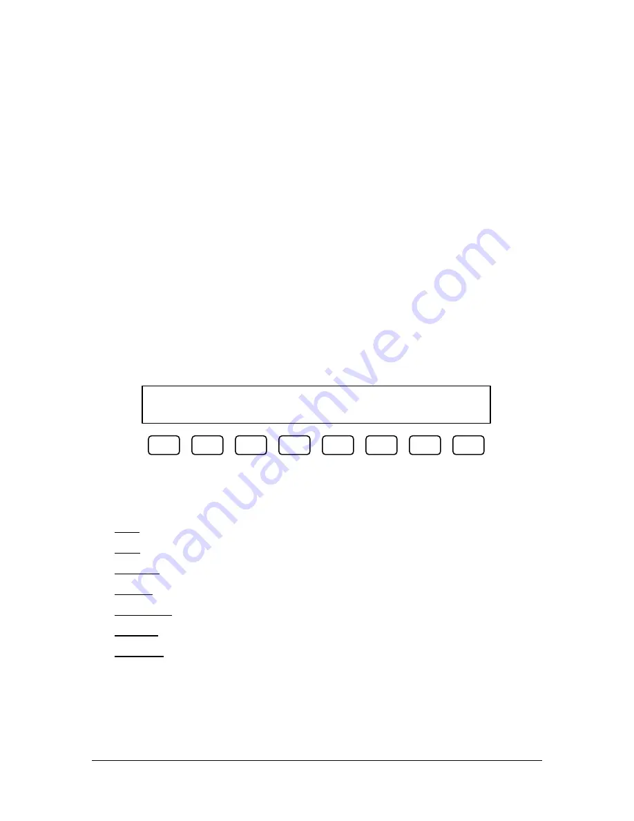
Flow control mode is typically accessed through the Cycle Stop menu using the F2 function key. If access
to Flow Control mode is not achieved through Cycle Stop, or if more than one flow monitor is installed on
the workcell, documentation in the Optional Equipment section of the Operator’s Guide will provide details
on these options.
Flow
00.00cc
DEV=00.0%
Error
EXIT
UP
DOWN
UP
DOWN
*ON
OFF
F1
F2
F3
F4
F5
F6
F7
F8
Flow mode allows control over the flow monitor data that is used as a process check only during Auto
Cycle. These settings are used to determine the material volume and whether or not it is excessive
unless
superceded by commands in a path program. The error selection turns the process verification check on and
off. The error ON/OFF selection cannot be overridden by commands in a path program.
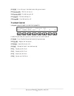
[F1] EXIT
– Leave Flow mode and return to Cycle Stop.
[F3] cc UP
– Increase the material target level. Maximum is 99 cc.
[F4] cc DOWN
– Decrease the material target level. Minimum is 0.00 cc.
[F5] DEV UP
– Increase the allowable deviation. Maximum is 99%.
[F6] DEV DOWN
– Decrease the allowable deviation. Minimum is 0%.
[F7] Error ON
– Turn the material flow error checking on. (default)
[F8] Error OFF
– Turn the material flow error checking off.
Summary of Contents for PVA2000
Page 9: ...Notes ...

