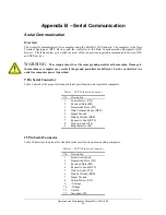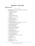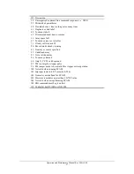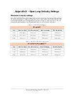
Operation and Maintenance Manual Rev M(ii) 4/03
- 45 -
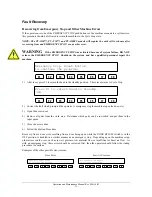
1) Turn the power OFF and open the electrical enclosure.
2) Disconnect all the cables from the DMC-1500 controller and remove the controller from the drawer.
3) Remove the protective metal cover.
4) Avoid any danger of static discharge damage during handling of the controller circuit board and
EEPROM chips by wearing a ground strap.
5) Remove the EEPROM chips from the controller and replace with new EEPROMs, making sure to place
the L and H labeled chips in the L and H labeled sockets.
6) Perform a Master Reset so that the controller recognizes the new EEPROM firmware. Please refer to
the Controller Master Reset procedure on page 44.
7) Return the old EEPROMs to Precision Valve & Automation. PVA must have the old EEPROMs back
in order to continue service in the future.
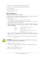
Power Check
(All models except PVA250™, PVA750™, PVA2000C™)
If the expected voltages are not present in the following tests
TURN THE MACHINE OFF
IMMEDIATELY
. Permanent damage to the components may occur.
1) Remove all of the fuses in the enclosure, except for FU-1.
2) Disable the enclosure power safety switch.
3) Turn the machine ON.
4) Use a DMM (Digital Multi Meter) to check the AC power in the machine. There should be 110-120
VAC between the 100 and 101 terminals. If not, turn off the power and check that FU-1 is installed
and operational.
5) Turn the machine OFF.
6) Install all of the fuses in the enclosure.
7) Push
the
EMERGENCY STOP
push button in.
8) Turn the machine ON.
9) CRM-1 and CRM-2 should be DISENGAGED.
10) Check for 5 VDC between 304 (+) and 303 (-).
11) Check for 24 VDC between 306 (+) and 302 (-).
12) Check for 0 VDC between 307 (+) and 302 (-).
13) Pull the
EMERGENCY STOP
push button out.
14) Put a jumper wire between terminal 4 on the 5 V Monitor relay SSR-5 relay and any 304 terminal block
(this will engage the SSR-5 relay). If the SSR-5 relay LED is not on, there may be a problem with the
SSR-5 relay or the wiring on the coil side.
15) CRM-1 and CRM-2 should be ENGAGED. If not, check the next section (Door Interlock Check) for
machines equipped with doors.
16) Check for 24 VDC between 307 (+) and 302 (-).
Summary of Contents for PVA2000
Page 9: ...Notes ...

