


Operation and Maintenance Manual Rev M(ii) 4/03
- 47 -
13) Move the W axis in the positive direction and display the current position.
14) Move the W axis in the negative direction and display the current position.
15) Turn the machine OFF.
16) Reconnect the motor power cables.
17) Turn the machine ON.
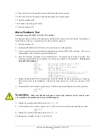
Motor Feedback Test
(All models except PVA250™, PVA750™, PVA2000C)
Use this procedure to verify that the motor power and hall effect sensors are wired correctly. If a problem is
found with any of the axes, repair and report to the production supervisor.
1) Turn the machine ON.
2) Enable
the
EMERGENCY STOP
button. This cuts the power to the amplifiers.
3) Open a terminal program and establish communication with the DMC-1500 controller. This can be
accomplished via the ‘terminal’ option in PathMaster®.
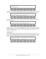
4) Enter the following commands via the terminal screen. The motors may be wired incorrectly. The
following program limits the acceptable error and power available to the amplifiers.
This protects
personnel and equipment.
OE*=1
Off on error enabled for all axes.
ER*=1000
Error limit for all axes.
TL*=1
Torque limit of 1 for all axes.
SP*=5000
Set the speed.
AC*=10000
Set the acceleration.
DP*=0
Define the current position as (0, 0, 0, 0).
SB5
Enable power (only on machines without a
POWER ON button).
SH
Apply power to the servo motors.
5) Release
the
EMERGENCY STOP
push button. Push the
POWER ON
button (if present) so it lights up.
This restores power to the amplifiers. Care must be taken because any of the axes can move at this
time.
6) Command the X axis to make a positive move. If the axis runs away debug and repeat the procedure.
PRX=2000
BGX
WARNING
Make sure that the workspace is clear of any obstacles. In the event of a run-
away condition, the machine may be irreversibly damaged.
7) Display the current position and position error.
TP; TE
.
8) Command the X axis to make a negative move. If the axis runs away debug and repeat the procedure.
PRX=-2000
BGX
9) Display the current position and position error.
TP; TE
.
10) Repeat step 6 through 9 for the Y, Z and W axes.
Summary of Contents for PVA2000
Page 9: ...Notes ...


