Operation and Maintenance Manual Rev M(ii) 4/03
- 54 -
Appendix B – Serial Communication
Serial Communication
Overview
The workcell communicates with a computer using the EIA RS-232C standard. The computer is the Data
Terminal Equipment (DTE Device) and the controller is the Data Communications Equipment (DCE
Device). The tables below give a brief overview of the connections required to communicate between DTE
and DCE devices.
WARNING
The computer must be at the same ground potential as the machine. Damage to
the machine or computer may result if the ground potentials are different. Use the workcell service
outlet for computer power if provided.
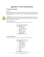
9 Pin Serial Connector
Table 9 describes the pinout for standard serial ports found on most portable computers.
Table 9 – DTE 9 Pin Serial Connector
Pin Description
1
Carrier Detect (CD)
2
Received Data (RD)
3
Transmitted Data (TD)
4
Data Terminal Ready (DTR)
5 Signal
Ground
6
Data Set Ready (DSR)
7
Request to Send (RTS)
8
Clear to Send (CTS)
9
Ring Indicator (RI)
25 Pin Serial Connector
Table 10 describes the pinout for standard serial ports found on most desktop computers.
Table 10 – DTE 25 Pin Serial Connector
Pin Description
1 Protective
Ground
2
Transmitted Data (TD)
3
Received Data (RD)
4
Request to Send (RTS)
5
Clear to Send (CTS)
6
Data Set Ready (DSR)
7 Signal
Ground
8
Carrier Detect (CD)
9 +Voltage
10 -Voltage
11 Unused
12 Secondary
CD
Summary of Contents for PVA2000
Page 9: ...Notes ...


