Operation and Maintenance Manual Rev M(ii) 4/03
- 59 -
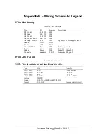
Appendix E – Wiring Schematic Legend
Wire Numbering
Table 16 – Wire Numbering
Type ID
Example
Description
DC Control
400 - 599
400
DC Supply
300 - 399
300
AC Control
200 - 299
200
AC Control Power
100 - 199
100
AC Supply Power
nLm
1L2
Segment 1 of AC Supply Phase 2
Ground GND
GND
Neutral NEU
NEU
AC or DC Motor
nTm
1T2
Motor 1, phase 2
Inputs
n1mm
1101
Module 1, Input 01
Outputs
n0mm
2001
Module 2, Output 02
Connector Jnnn/mm
J100/5
Connector 100, pin 5
Wire Color Code
Table 17 – Wire Color Code
NOTE: This color code does not apply to multi-conductor cables.
Type Color
Example
DC (<150 V)
BLUE
0 Vdc, 80 Vdc
DC (>150 V)
BLACK
200 Vdc
AC (<150 V)
RED
120 Vac
AC (>150 V)
BLACK
208 Vac, 480 Vac
Neutral WHITE
Ground
GREEN or GREEN with YELLOW
Remote
YELLOW
Remote control circuit
Summary of Contents for PVA2000
Page 9: ...Notes ...


